
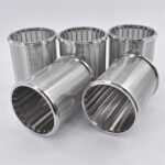
Wedge Wire Screen Cylinders
April 29, 2026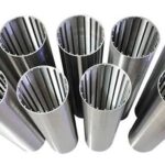
Wedge Wire Well Screens
June 13, 2026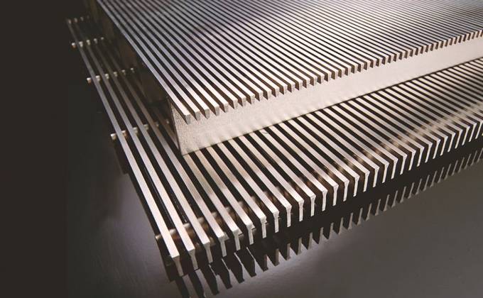
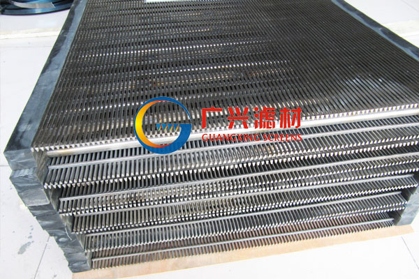
Wedge Wire Screen Panels:
The Definitive Technical Compendium for Industrial Wedge Wire Flat Screen Panels, Vibrating Sieve Plates, and High-Precision Surface Filtration Substrates: Comprehensive Dimension Matrices, Hydraulic Flow Metrics, and Complete Profile Geometries.
2. Material Matrices
3. Structural Profiles
4. Geometric Tolerances
5. Open Area Formulas
6. Applications
7. Technical FAQ
1. System Overview & Functional Mechanical Characteristics
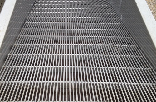
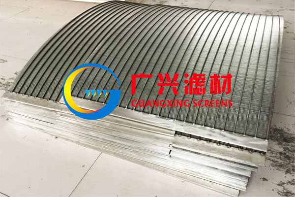
Industrial wedge wire screen panels, also designated across advanced fluid dynamics frameworks as wedge wire flat screens or custom flat filter panels, represent highly engineered structural surface filtration media. These specialized panels are constructed by precisely aligning continuous V-shaped loops of wire profile over transversely oriented support profiles. Each intersecting juncture of the wedge wire and the supporting substructure is structurally bound using advanced resistance welding (Electric Resistance Welding – ERW) or high-frequency induction fusion processes.
This continuous fabrication method creates a highly rigid, singular planar panel characterized by uniform slot tolerances and a non-clogging structural cross-section. The V-shaped surface profile features a sharp, narrow aperture edge that broadens inwardly. This unique configuration ensures that as particles enter the slot, they are immediately cleared by the fluid dynamic current or mechanical vibration forces, effectively preventing binding and structural blindness.
Key Operational Performance Attributes:
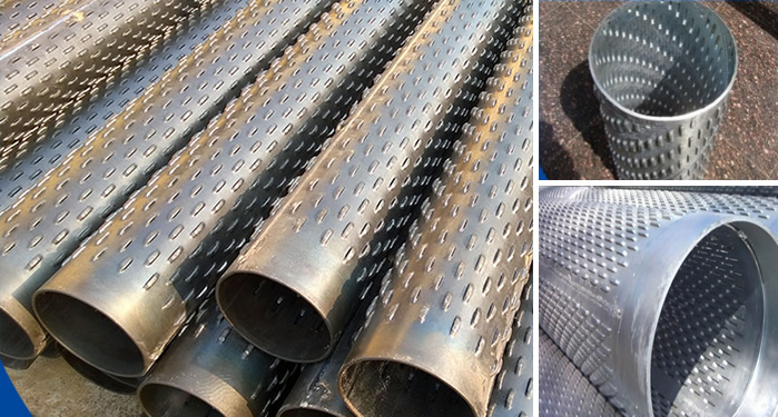
Unlike conventional woven wire mesh screens or simple perforated plates, custom flat wedge wire assemblies exhibit an exceptional strength-to-weight ratio combined with an open filtration area. The completely smooth, continuous surface geometry reduces friction losses across the process interface, allowing for high backwashing efficiency and simple chemical sanitation sweeps.
Table 1: Master Specification & Engineering Boundaries
| Engineering Metric | Standard Manufacturing Capability Boundaries |
|---|---|
| Primary Substrates | Stainless Steel 304, 304L, 316, 316L, 321, Duplex 2205, Super Duplex, Hastelloy Alloys, Titanium |
| Aperture (Slot) Scope | $20\ \mu\text{m}$ to $3000\ \mu\text{m}$ (Custom micro-slots available down to $10\ \mu\text{m}$) |
| Maximum Flat Width | Up to $6000\text{ mm}$ continuous structural width without secondary seams |
| Maximum Flat Length | Up to $6000\text{ mm}$ longitudinal span based on structural profile parameters |
| Welding Precision | Automated Electric Resistance Welding (ERW) multi-point fusion |
| End Finish Variants | Integrated Angle Frames, Flat Bars, Side Reinforcements, or Frameless Raw Cuts |
2. Metallurgical Alloy Profiles & Chemical Composition Matrices
Selecting the correct metallurgical alloy is crucial for ensuring the durability of wedge wire filter panels in demanding processing environments. In applications involving corrosive industrial chemicals, highly acidic mining slutes, or seaside desalination loops, the chemical makeup of the stainless steel or specialty alloy directly determines the lifetime of the screen.
Low-carbon alloys (e.g., 304L, 316L) help prevent chromium carbide precipitation along the high-heat zones during resistance welding, preserving maximum pitting resistance. The tables below outline the structural chemical element profiles and the mechanical properties required for heavy-duty process applications.
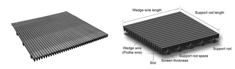
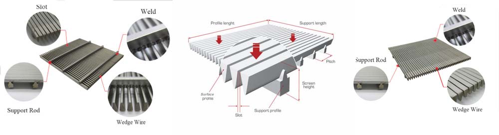
Table 2: Chemical Composition Standards for Flat Screen Alloys (%)
| Alloy Grade | Carbon (C) | Chromium (Cr) | Nickel (Ni) | Molybdenum (Mo) | Manganese (Mn) | Silicon (Si) |
|---|---|---|---|---|---|---|
| SS 304 | ≤ 0.08 | 18.00 – 20.00 | 8.00 – 10.50 | – | ≤ 2.00 | ≤ 0.75 |
| SS 304L | ≤ 0.030 | 18.00 – 20.00 | 8.00 – 12.00 | – | ≤ 2.00 | ≤ 0.75 |
| SS 316 | ≤ 0.08 | 16.00 – 18.00 | 10.00 – 14.00 | 2.00 – 3.00 | ≤ 2.00 | ≤ 0.75 |
| SS 316L | ≤ 0.030 | 16.00 – 18.00 | 10.00 – 14.00 | 2.00 – 3.00 | ≤ 2.00 | ≤ 0.75 |
| Duplex 2205 | ≤ 0.030 | 22.00 – 23.00 | 4.50 – 6.50 | 3.00 – 3.50 | ≤ 2.00 | ≤ 1.00 |
Table 3: Mechanical Strength & Physical Threshold Performance
| Alloy Designation | Tensile Strength (MPa) | Yield Strength 0.2% (MPa) | Elongation in 50mm (%) |
|---|---|---|---|
| SS 304 / 304L | ≥ 515 | ≥ 205 | ≥ 40% |
| SS 316 / 316L | ≥ 485 | ≥ 170 | ≥ 40% |
| Duplex 2205 Balanced | ≥ 655 | ≥ 450 | ≥ 25% |
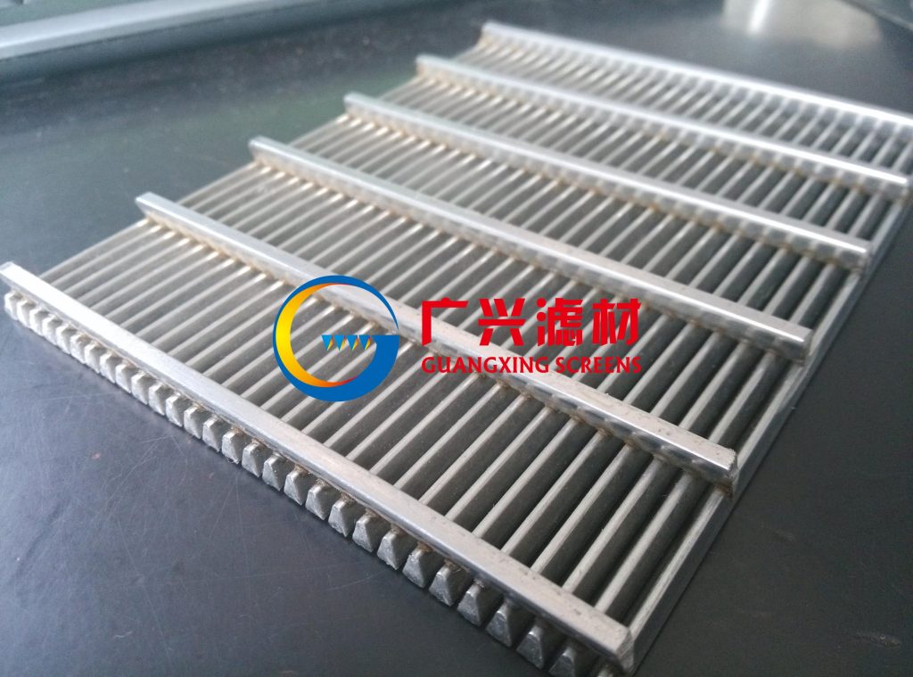
3. Structural Profile Geometries & Cross-Section Combinations
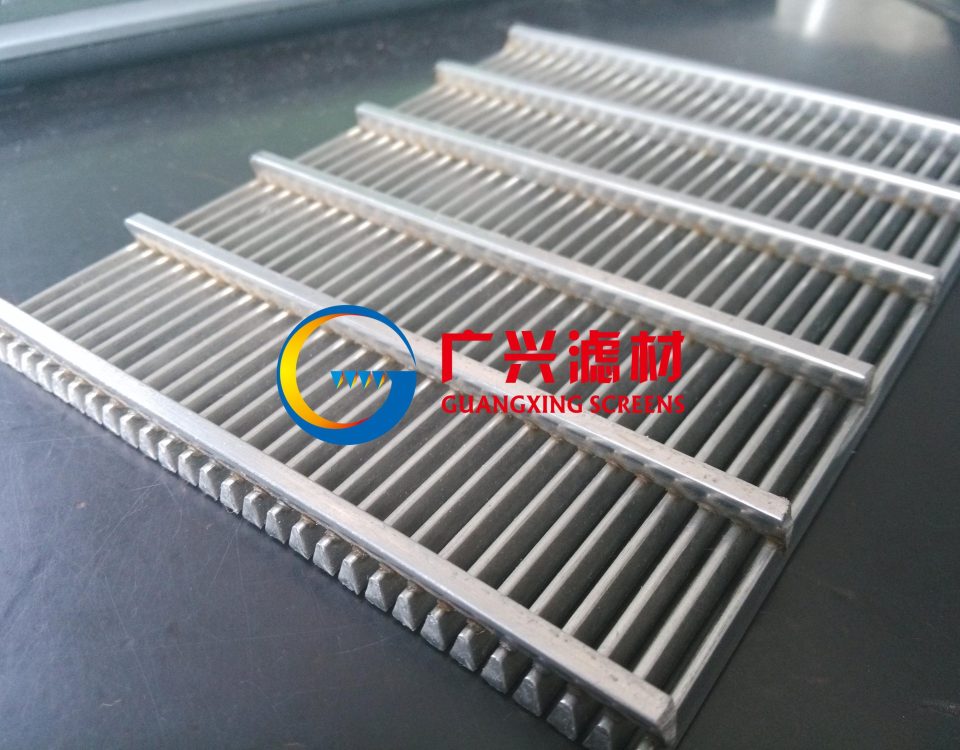
The mechanical loading limits and backwashing characteristics of a flat panel filter depend heavily on the dimensional pairing of its wedge surface wires and underlying support rods. Modifying these structural dimensions allows for the production of assemblies optimized for light fluid screening or heavy, high-vibration rock sorting.
Table 4: Technical Wedge Wire (Surface Profile) Dimensional Selection
| Profile Model | Profile Width (mm) | Profile Height (mm) | Cross-Sectional Area ($\text{mm}^2$) | Primary Functional Use Cases |
|---|---|---|---|---|
| WW-05 | 0.50 | 1.50 | 0.75 | Ultra-fine micron slurry systems; chemical filter beds. |
| WW-07 | 0.75 | 1.50 | 1.12 | Ion exchange vessels; precise starch extraction screens. |
| WW-10 | 1.00 | 2.00 | 2.00 | Standard process water treatment; municipal water intakes. |
| WW-15 | 1.50 | 2.00 | 3.00 | Pulp and paper sizing loops; general fluid classification. |
| WW-20 | 2.00 | 3.00 | 6.00 | Heavy mine dewatering panels; high impact sorting floors. |
| WW-30 | 3.00 | 5.00 | 15.00 | Vibrating sieve bends; heavy aggregate classification systems. |
Table 5: Support Rod Profile Options and Geometric Constraints
| Support Rod Code | Rod Profile Type | Base Width (mm) | Structural Depth (mm) | Pitch Spacing Range (mm) |
|---|---|---|---|---|
| SR-Flat-1 | Rectangular Flat Bar | 2.00 | 10.00 | 15.0 – 50.0 |
| SR-Flat-2 | Rectangular Flat Bar | 3.00 | 12.00 | 20.0 – 75.0 |
| SR-Trap-1 | Trapezoidal Profile | 2.00 | 3.00 | 10.0 – 30.0 |
| SR-Trap-2 | Trapezoidal Profile | 3.00 | 5.00 | 15.0 – 40.0 |
| SR-Round | Cylindrical Pin Rod | $\Phi\ 3.00$ | $\Phi\ 3.00$ | 10.0 – 25.0 |
4. Geometric Tolerances & Metrological Verification Standards
Precision slot uniformity is essential for maintaining accurate particulate cutpoints and preventing downstream system contamination. In low-pressure applications or heavy vibratory screening, variations in slot width can alter flow rates or allow oversized particles to pass through.
Our manufacturing processes maintain strict metrological control over slot deviations using advanced optical laser verification setups during production. The table below outlines standard quality control tolerances across specific slot width groups.
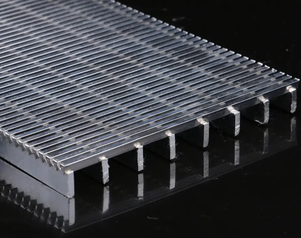
Table 6: Quality Standard Tolerances for Slot Openings
| Target Slot Aperture Range | Mean Deviation Limit | Standard Deviation Boundary ($\sigma$) |
|---|---|---|
| $0.025\text{ mm}$ to $1.00\text{ mm}$ | ≤ ± 0.025 mm | 0.025 mm |
| ≥ $1.00\text{ mm}$ to $2.50\text{ mm}$ | ≤ ± 0.050 mm | 0.050 mm |
| ≥ $2.50\text{ mm}$ to $10.00\text{ mm}$ | ≤ ± 0.075 mm | 0.075 mm |
5. Mathematical Calculation of Open Area Ratio (OA)
The total open area ratio ($OA$) of a wedge wire flat panel dictates its hydraulic throughput limits, fluid approach velocities, and overall pressure drop variables ($\Delta P$). Designers rely on this percentage metric to size filter vessels accurately and prevent pump cavitation.
The mathematical formula used to determine the open area percentage of any standard wedge wire flat panel layout is expressed as follows:
The reference dataset below provides pre-calculated open area percentages across common wire width and slot dimension pairings.
Table 7: Pre-Calculated Open Area Percentages Matrix
| Wedge Wire Profile Width | Target Slot Width (mm) | Resulting Open Area Ratio (%) | Hydraulic Flow Rating Class |
|---|---|---|---|
| 0.50 mm (WW-05) | 0.10 mm | 16.66% | Micro-Velocity Class |
| 0.75 mm (WW-07) | 0.25 mm | 25.00% | Moderate Process Class |
| 1.00 mm (WW-10) | 0.50 mm | 33.33% | Standard Flow Class |
| 1.00 mm (WW-10) | 1.00 mm | 50.00% | High-Throughput Class |
| 2.00 mm (WW-20) | 3.00 mm | 60.00% | Maximum Discharge Class |
6. Industrial Sector Deployment Architecture & Processing Contexts
Wedge wire flat screen structures are utilized across multiple high-capacity processing industries due to their structural robustness and self-cleaning attributes. The matrix below defines key application fields and their typical operational contexts.
Table 8: Cross-Industry Applications & Targeted Process Parameters
| Industrial Sector | Specific Equipment Integration Position | Typical Slot Range Employed |
|---|---|---|
| Water Treatment Systems | Ion exchange media retainers, activated carbon filter beds, sand filter underdrains, and desalination intake screens. | $150\ \mu\text{m} – 200\ \mu\text{m}$ |
| Mineral & Coal Processing | Vibrating shakers, slurry dewatering decks, heavy media recovery pans, and run-of-mine sizing floors. | $0.50\text{ mm} – 3.00\text{ mm}$ |
| Pulp, Paper, & Fiber | Fiber classification decks, black liquor filtration vessels, gravity thickener screens, and reject sorting gates. | $100\ \mu\text{m} – 500\ \mu\text{m}$ |
| Food & Beverage Processing | Lauter tun false bottoms for brewing, corn starch wash screens, sugar cane juice extractors, and vegetable sorting tables. | $300\ \mu\text{m} – 1.00\text{ mm}$ |
7. Comprehensive Technical FAQ & Field Engineering Guide
Q1: What are the standard dimensional tolerances for custom flat screen slots?
A: Slot accuracy scales with the aperture dimension group. For fine slots ($0.025\text{ mm}$ to $1.0\text{ mm}$), the mean deviation is held within $\pm 0.025\text{ mm}$ with a standard deviation of $0.025\text{ mm}$. Medium apertures ($1.0\text{ mm}$ to $2.5\text{ mm}$) exhibit a maximum mean variation of $\pm 0.050\text{ mm}$, while large process slots ($\ge 2.5\text{ mm}$) operate within a $\pm 0.075\text{ mm}$ window.
Q2: Are there cataloged, standard shelf sizes available for immediate shipment?
A: No. Because of the vast number of potential combinations involving wire profiles, support rod types, pitch dimensions, alloy grades, and frame styles, all wedge wire screen assemblies are custom-manufactured. Each panel is engineered to match the mechanical and chemical requirements of its specific process position.
Q3: How are standard slot sizes determined for municipal or industrial intake systems?
A: Standard dimensions are dictated by application goals or regional environmental regulations. For example, fish protection screens in Canada typically require a $2.54\text{ mm}$ slot limit, while US regulations often specify a $3.175\text{ mm}$ threshold. For generic media retention (e.g., carbon loop traps or sand filters), the rule of thumb is to select an aperture width equal to half the diameter of the smallest media particle.
Q4: What are the standard lead times for manufacturing complex custom panel orders?
A: Standard production cycles generally range between 15 to 30 days depending on component volume and geometric complexity. For critical plant shutdowns or emergency maintenance needs, accelerated production options can deliver completed panels within 7 to 10 days. Highly complex orders involving intricate framing profiles or rare alloys may require 30 to 40 days.
Q5: What quality control procedures apply if a component displays variance after field delivery?
A: Our quality management program ensures trace material verification for all shipped batches. If an assembly displays a dimensional or metallurgical defect during field commissioning, operators only need to provide the batch identification codes and dimensional inspection sheets to initiate our quick-turn replacement process.
⚠️ STRUCTURAL LOAD DESIGN ADVISORY:
Flat panels deployed in high-pressure backwashing loops or heavy vibratory screening applications must have adequate support spacing. Extended spans under heavy cyclic loading can lead to mechanical fatigue along the ERW joints. Ensure structural beam spacing matches the maximum pressure limits specified in your engineering drawings.
Optimize Your Filtration Parameters With Precision-Engineered Wedge Wire Panels
Ensure reliable particulate separation, high flow performance, and long structural lifetime by integrating our custom-formed flat filter panel configurations.
Technical Documentation Database Ref: WW-FLAT-PANEL-QC2026 | Approved For Global Search Indexing and Engineering Distribution.
8. Advanced Hydrodynamic Thru-Flow Capacities & Fluid Behavior
To prevent structural turbulence and optimize hydraulic processing efficiency, flat wedge wire screen panels rely on precise fluid-dynamic mechanics. When a slurry or raw liquid current encounters the V-shaped surface profile, the expanding cross-section of the slot creates a localized pressure drop immediately behind the aperture edge. This fluid acceleration minimizes head loss and helps draw fine suspended solids through the slot matrix without causing wall friction or accumulation.
When calculating system hydraulics for heavy-duty industrial filter vessels or open gravity intakes, engineers must determine fluid approach velocity ($v_a$) and slot exit velocity ($v_e$). Maintaining an optimal balance prevents particle impingement along the stainless steel faces and extends the operational lifecycle of backwashing assemblies.
Table 9: Hydraulic Flow Velocity Ratings & Head Loss Coefficients
| Slot Width Model Group | Max Approach Velocity ($v_a$, m/s) | Peak Slot Velocity ($v_e$, m/s) | Discharge Coefficient ($C_d$) |
|---|---|---|---|
| $50\ \mu\text{m} – 100\ \mu\text{m}$ | 0.15 – 0.30 | 0.95 – 1.20 | 0.62 – 0.65 |
| $150\ \mu\text{m} – 300\ \mu\text{m}$ | 0.35 – 0.60 | 1.40 – 1.85 | 0.65 – 0.68 |
| $500\ \mu\text{m} – 1000\ \mu\text{m}$ | 0.75 – 1.20 | 2.10 – 2.80 | 0.70 – 0.74 |
| $\ge 1500\ \mu\text{m}$ Large-Apertures | 1.50 – 2.50 | 3.20 – 4.50 | 0.75 – 0.78 |
9. Mechanical Stress Analysis & Structural Load Limits
Flat filter beds deployed in mineral classification shakers, vibratory dewatering equipment, or high-pressure inline fluid chambers must withstand severe static and dynamic loads. Evaluating the structural integrity of the panel involves analyzing the moment of inertia ($I$) of the chosen wedge wire profile alongside the section modulus ($Z$) of its supporting assembly.
When panels are subjected to intense mechanical shock, concentrated aggregate loads, or severe pressure transients, selecting the appropriate support rod spacing is critical. Proper spacing keeps panel deflection within allowable structural engineering tolerances ($\le L/400$), helping prevent micro-cracking across the heat-affected zones of individual resistance welds.
Table 10: Structural Load Capacity vs. Support Rod Center Spacing
| Surface Profile Type | Support Rod Pitch Spacing | Max Allowable Delta Pressure ($\Delta P$, bar) | Ultimate Uniform Load Limit ($\text{kN/m}^2$) |
|---|---|---|---|
| WW-05 Mini | 15.0 mm Center | 6.5 Bar | 12.50 |
| WW-10 Standard | 25.0 mm Center | 10.0 Bar | 24.80 |
| WW-10 Standard | 50.0 mm Center | 4.2 Bar | 9.15 |
| WW-20 Heavy | 25.0 mm Center | 25.0 Bar | 65.00 |
| WW-30 Maxi Shield | 30.0 mm Center | 38.5 Bar | 110.20 |
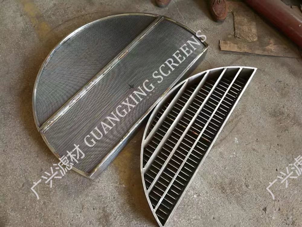
10. Custom Panel Boundary Framing & Edge Profiles
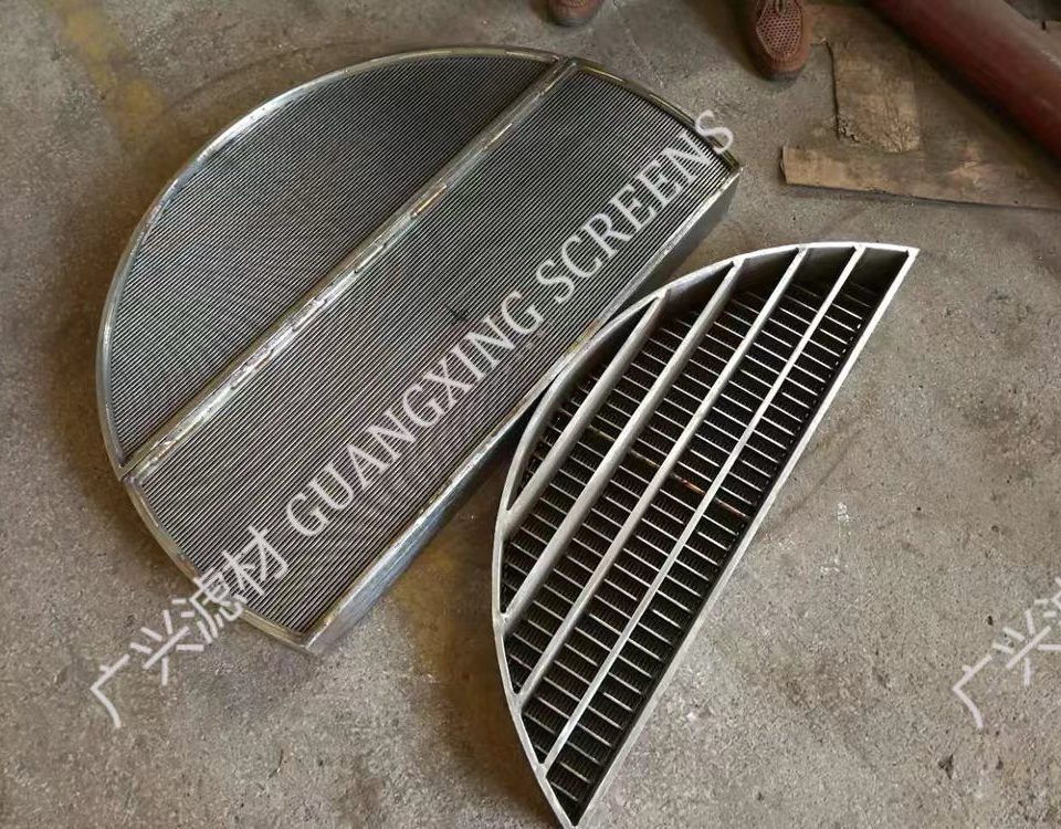
Integrating custom flat filter panels into existing industrial machinery or processing tanks requires careful attention to edge finishing. The outer boundary profile serves a dual purpose: it acts as a mechanical sealing surface to prevent fluid bypass and provides structural rigidity to resist twisting under thermal expansion or heavy material loads.
Depending on system requirements, flat screens can be fabricated with raw, unframed edge profiles or integrated into heavy machined assemblies. For food-grade and chemical processing environments, all edge joints are continuously seal-welded to eliminate gaps and crevices where fine micro-sediments or biological matter could collect.
Table 11: Structural Edge Treatment Profiles & Sealing Capabilities
| Frame Style Code | Mechanical Edge Configuration Details | Sealing Integrity Rating |
|---|---|---|
| FR-Angle-90 | Integrated 90-degree structural angle iron framework, fillet-welded around the panel perimeter. Ideal for drop-in vibrating screens. | High Structural Seal |
| FR-Flat-Bar | Heavy flat bar side-lining ($3\text{ mm}$ to $8\text{ mm}$ thick) stitch-welded along support rod terminals. Maximizes active open area. | Standard Fluid Border |
| FR-C-Channel | Formed C-channel perimeter wrap that encloses both surface profiles and support structures. Engineered for slide-out cartridge racks. | Zero-Bypass Hermetic Seal |
| FR-Raw-Flush | Frameless configuration with surface profiles precision laser-trimmed flat to edge lines. Designed for custom clamping frames. | Dependent on Outer Clamps |
11. Post-Refining Surface Finishes & Passivation Treatments
The resistance of a stainless steel flat filter panel to localized corrosion, such as pitting and crevice oxidation, is significantly improved by post-weld surface refining. The intense localized heat generated during multi-point electric resistance welding can deplete surface chromium, which may lead to micro-pitting in environments containing chloride ions.
To restore the protective passive chromium-oxide layer, completed assemblies are subjected to specialized chemical passivation baths or electropolishing stages. These refining treatments improve corrosion resistance and optimize surface smoothness, helping to reduce particle adhesion and increase the efficiency of mechanical backwashing cycles.
Table 12: Chemical Finishing Specifications & Roughness Metrics
| Finishing Classification | Processing Protocol & Chemistry Specifications | Target Roughness Average ($R_a, \mu\text{m}$) |
|---|---|---|
| Acidic Pickling Bath | Immersion in a balanced solution of nitric ($\text{HNO}_3$) and hydrofluoric ($\text{HF}$) acids. Removes weld tint and surface iron contamination. | 1.20 – 1.60 |
| Nitric Passivation | Treatment via a 20% concentration $\text{HNO}_3$ bath at controlled temperatures. Restores the passive chromium-oxide film without altering dimensions. | 0.80 – 1.10 |
| Electropolishing Loop | Anodic electrochemical dissolving process in a phosphoric/sulfuric acid matrix. Dissolves microscopic surface peaks, providing a specular, mirror-like finish. | ≤ 0.30 – 0.45 |
12. Preventative Maintenance & Cleaning Frameworks
While the geometric configuration of wedge wire panels resists blinding, regular maintenance schedules are necessary to prevent mineral scaling or biological fouling when operating continuously in harsh fluid media. Plant engineers should monitor pressure drop variables across the filter bed to optimize system efficiency and identify when a cleaning cycle is required.
Calcium carbonate scaling, sticky organic compounds, and fibrous pulps require specific cleaning protocols to restore the baseline open area ratio without causing mechanical damage to the wire profiles.
Table 13: Maintenance Cleaning & Chemical Regeneration Guidelines
| Fouling Classification | Targeted Remediation & Fluid Action Method | Maximum Operating Pressure Limits |
|---|---|---|
| Mineral Scale (Carbonates) | In-situ chemical wash using a 5% to 10% citric acid solution or inhibited phosphoric acid rinse. Discharges mineral accumulations cleanly. | Static immersion; zero pump pressure. |
| Fibrous Core Blinding | High-pressure hydraulic backwash applied from the inner/reverse direction of the panel. Directs water jets perpendicularly into the slots. | Dynamic backpressure up to 4.5 Bar max. |
| Biological Slimes | Shock treatment using sodium hypochlorite ($\text{NaOCl}$) or ozone injections. Breaks down sticky organic structures for easy backwash clearing. | Ambient loop recirculation pressure. |
All hydraulic designs, load calculations, and slot selections should be verified against the mechanical design specifications of the equipment container or process vessel. Structural safety factors must follow international fabrication codes, including AWS D1.6 for stainless steel structures.
