Wedge Wire Screen Panels Custom
May 24, 2026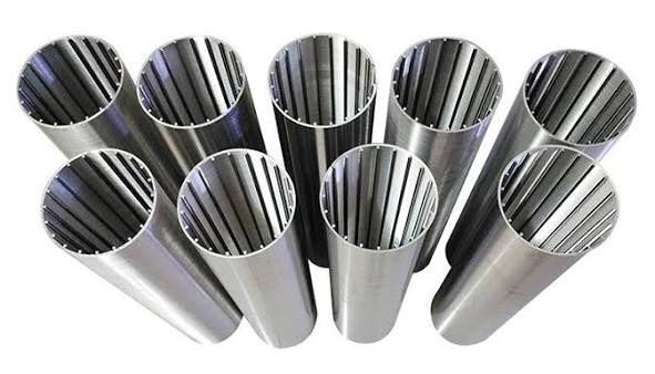
Premium B2B Industrial Specification Data Sheet
High-Capacity Wedge Wire Well Screens
Advanced Continuous-Slot All-Welded Johnson Type Screens. Engineering Guide to Metallurgical Grade Options, Fluid Flow Dynamics, Structural Collapse Resistance Matrices, and Custom Fabrication Tolerances.
Quick Technical Overview for Engineers
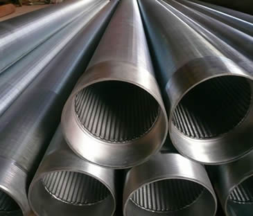
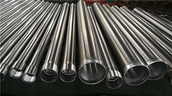
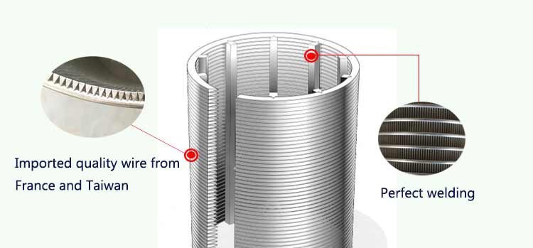
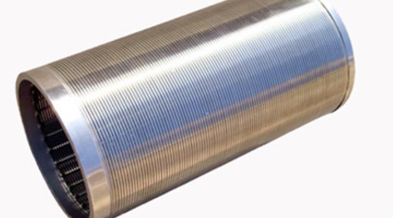
Wedge Wire Well Screens (commonly known as Johnson Type Screens) are advanced, non-clogging filtration arrays engineered by helically wrapping a continuous V-shaped or wedge-shaped profile wire around an internal framework of longitudinal support rods. Utilizing computer-controlled, high-intensity fusion all-weld technology at every intersecting point, these cylinders feature exceptional mechanical strength, a high open area coefficient (up to 60%), and precise slot dimensions down to 0.02 mm. They provide efficient sand control, minimize drawdown friction, and optimize fluid extraction across water, oil, and gas exploration fields globally.
• 2. Architectural Advantages & Non-Clogging Mechanics
• 3. Metallurgical Grades & Chemical Integrity
• 4. Surface Profile Wires & Support Rod Geometries
• 5. Flow Configuration Dynamics: FOTI vs. TITO
• 6. Structural Dimensional Range & Blueprint Limits
• 7. Open Area Calculation & Hydrodynamic Slot Matrix
• 8. Mechanical Load Limits & Collapse Resistance
• 9. End Connection Mechanics & Joint Configurations
• 10. Specialized Product Configurations & Variations
• 11. Quality Control Protocols & Non-Destructive Testing
• 12. B2B International Procurement & Logistics Mapping
1. Scope of Application & Structural Core
Continuous-slot wedge wire well screens represent the definitive technological solution for sand-bed management, liquid-solid phase separation, and fluid intake optimization in high-yield extraction wells. Operating under challenging downhole parameters, these components serve as the primary defensive barrier against gravel pack displacement and structural sand entry into deep casing wells. Their heavy industrial application covers deep water well drilling, oil and gas production lines, geothermal energy capture arrays, industrial waste purification infrastructure, and petrochemical processing reactors requiring excellent stability under severe thermal and mechanical stresses.
2. Architectural Advantages & Non-Clogging Mechanics
The superior operational performance of the wedge wire design over conventional slotted pipe or punched hole configurations relies on two primary mechanical principles:
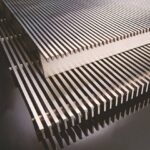
True Non-Clogging V-Geometry
The unique inward-widening, V-shaped cross-section creates a continuous, converging throat line. Any particle that clears the narrow exterior entry gap travels freely into the internal chamber without getting wedged within the slot depth. This design facilitates efficient reverse back-flushing, lowers maintenance downtime, and preserves long-term intake capacity.
Hydrodynamic Efficiency
The consecutive slot configuration yields an exceptionally high open-area coefficient. By maximizing fluid entry area, intake velocity drops to safe thresholds, reducing entrance friction losses and preventing high-pressure sand transport. Consequently, pump energy costs are minimized while significantly extending well life.
3. Metallurgical Grades & Chemical Integrity Matrix
Downhole environmental elements like dissolved hydrogen sulfide ($H_2S$), carbon dioxide ($CO_2$), and elevated chloride levels require precise metallurgical selection. Using sub-standard alloy blends accelerates stress-corrosion cracking ($SCC$) and micro-pitting along slot margins, leading to premature well collapse. The table below details our primary corrosion-resistant engineering alloys:
| Alloy Material Grade | Carbon (C) max | Chromium (Cr) | Nickel (Ni) | Molybdenum (Mo) | Nitrogen (N) | PREN Value |
|---|---|---|---|---|---|---|
| AISI 304 (UNS S30400) | 0.08% | 18.0 – 20.0% | 8.0 – 10.5% | — | — | ~19.0 |
| AISI 304L (UNS S30403) | 0.03% | 18.0 – 20.0% | 8.0 – 12.0% | — | — | ~19.0 |
| AISI 316 (UNS S31600) | 0.08% | 16.0 – 18.0% | 10.0 – 14.0% | 2.00 – 3.00% | — | ~25.0 |
| AISI 316L (UNS S31603) | 0.03% | 16.0 – 18.0% | 10.0 – 14.0% | 2.00 – 3.00% | — | ~25.0 |
| Duplex 2205 (UNS S32205) | 0.03% | 22.0 – 23.0% | 4.5 – 6.5% | 3.00 – 3.50% | 0.14 – 0.20% | ≧ 35.0 (High) |
| Hastelloy C276 (UNS N10276) | 0.01% | 14.5 – 16.5% | Base (~57%) | 15.0 – 17.0% | — | ≧ 64.0 (Extreme) |
Table 3.1: Ladle chemical analysis tracking constraints and Pitting Resistance Equivalent Number ($PREN = \%Cr + 3.3\%Mo + 16\%N$).
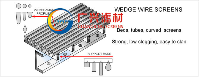
4. Surface Profile Wires & Support Rod Geometries
Customizing mechanical resistance profiles requires choosing matching face wire width metrics alongside corresponding internal support rods. Adjusting wire widths directly determines both aggregate filtering precision and flow path dimensions, while rod geometries establish structural collapse and tensile limits.
| Profile Wire Type | Standard Width Dimensions (mm) | Standard Height Dimensions (mm) | Internal Support Rod Variations |
|---|---|---|---|
| Type 0.9×1.9 | 0.90 mm | 1.90 mm | Triangular (V-Shape): 2.0×3.0mm, 3.0×5.0mm
Standard Round Wire: Φ 2.5mm, Φ 3.0mm, Φ 4.0mm Flat / Square Bar: 1.5x20mm, 2.0x25mm Teardrop Shape (High-Yield Filtration) |
| Type 1.19×2.24 | 1.19 mm | 2.24 mm | |
| Type 1.8×2.75 | 1.80 mm | 2.75 mm | |
| Type 2.28×3.56 | 2.28 mm | 3.56 mm | |
| Type 3.0×5.0 | 3.00 mm | 5.00 mm | Enhanced Heavy-Duty Anchors: 3.5×6.5mm, 4.0×6.5mm, 2.0×6.5mm High-Load Flats. |
| Type 4.0×6.0 | 4.00 mm | 6.00 mm | |
| Type 4.0×8.0 | 4.00 mm | 8.00 mm |
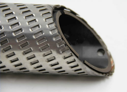
5. Flow Configuration Dynamics: FOTI vs. TITO
Depending on the direction of fluid intake or effluent processing, wedge wire filters must be designed according to one of two structural flow methodologies. Improper selection can cause reverse filtration drag, accelerating blockages:
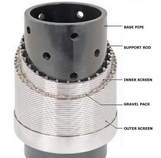
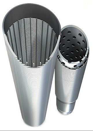
FOTI (Flow From Outside To Inside)
The standard layout for water and oil extraction wells. Fluid enters from the external gravel pack and travels inward. The flat surface faces outward, retaining sand on the shell exterior, while the internal support rods run longitudinally along the inner diameter.
TITO (Flow From Inside To Outside)
Typically applied in industrial separator drums, wastewater filtration, downhole internal pumping loops, and food processing systems. The smooth filtration face is located on the inner diameter, allowing internal scraping or screw transport mechanisms to move collected debris outward.
6. Structural Dimensional Range & Blueprint Limits
Manufacturing deep well filters requires strict control over concentricity and geometric deviations. Slight ovality across long sections causes joint binding during casing installation. The standardized production limits below govern structural runs:
| Dimensional Parameter Name | Standard Mill Range Capabilities | Strict Production Tolerances |
|---|---|---|
| Outer Cylinder Diameter (OD) | 25 mm — 1500 mm | ± 0.50 mm (Strict Precision) |
| Filter Slot Opening Gap | 0.02 mm — 3.00 mm | ± 0.015 mm (Downhole Grade) |
| Single Segment Length ($L$) | 100 mm — 6000 mm | ± 2.00 mm (End-to-End) |
| Ovality Deviation Limit | — | ≦ 0.8% of Nominal OD |
| Total Section Straightness Deviation | — | ≦ 1.50 mm per 6-Meter Length |
7. Open Area Calculation & Hydrodynamic Slot Matrix
The effective open area percentage ($OA$) dictates downhole velocity constraints. It is calculated utilizing the primary mathematical profile ratio:
To assist fluid engineering groups in planning precise drawdowns, the high-density lookup matrix below matches various profile configurations with their corresponding weight distributions and flow metrics:
| Nominal Screen OD | Wire Profile Size | Slot Gap Size | Open Area Coefficient | Theoretical Section Weight |
|---|---|---|---|---|
| Φ 89 mm (3.5″) | 1.5 x 2.0 mm | 0.25 mm | 14.28 % | 6.24 kg/m |
| Φ 89 mm (3.5″) | 1.5 x 2.0 mm | 0.50 mm | 25.00 % | 5.10 kg/m |
| Φ 114 mm (4.5″) | 2.0 x 3.0 mm | 0.30 mm | 13.04 % | 9.80 kg/m |
| Φ 114 mm (4.5″) | 1.8 x 2.7 mm | 0.75 mm | 29.41 % | 8.42 kg/m |
| Φ 168 mm (6.625″) | 2.2 x 3.5 mm | 0.50 mm | 18.51 % | 17.10 kg/m |
| Φ 168 mm (6.625″) | 1.8 x 2.7 mm | 1.00 mm | 35.71 % | 13.85 kg/m |
| Φ 219 mm (8.625″) | 2.2 x 3.5 mm | 0.75 mm | 25.42 % | 23.40 kg/m |
| Φ 219 mm (8.625″) | 2.2 x 3.5 mm | 1.50 mm | 40.54 % | 18.90 kg/m |
| Φ 273 mm (10.75″) | 3.0 x 5.0 mm | 1.00 mm | 25.00 % | 36.50 kg/m |
| Φ 273 mm (10.75″) | 2.2 x 3.5 mm | 2.00 mm | 47.61 % | 24.20 kg/m |
| Φ 323 mm (12.75″) | 3.0 x 5.0 mm | 1.20 mm | 28.57 % | 43.10 kg/m |
| Φ 323 mm (12.75″) | 3.0 x 5.0 mm | 2.00 mm | 40.00 % | 35.80 kg/m |
| Φ 406 mm (16.0″) | 3.2 x 6.0 mm | 1.50 mm | 31.91 % | 59.40 kg/m |
| Φ 508 mm (20.0″) | 3.2 x 6.0 mm | 2.00 mm | 38.46 % | 74.20 kg/m |
| Φ 610 mm (24.0″) | 3.2 x 6.0 mm | 2.50 mm | 43.85 % | 88.60 kg/m |
Table 4.1: High-density structural configuration map matching slot spacing intervals with section weights.
8. Mechanical Load Limits & Collapse Resistance
DOWNHOLE MECHANICAL COLLAPSE WARNING:
Deep horizontal completions and deep alluvial wells subject filtration screening elements to critical radial compression forces. If local formation pressure imbalances exceed the certified collapse point of the screen mesh, radial buckling will occur, destroying the wellbore.
To safely handle extreme downhole geological loads, our internal support frames are engineered to cross-sectional resistance profiles. Critical parameters are categorized below:
| Support Rod Density Class | Rod Spatial Pitch Interval | Ultimate Yield Strength Baseline | Certified Collapse Pressure Rating |
|---|---|---|---|
| Standard Duty Matrix | 12 — 16 mm Spacing | ≧ 515 MPa | 15 — 35 Bar Depth Limit |
| Heavy Reinforced Class | 8 — 11 mm Spacing | ≧ 550 MPa | 40 — 75 Bar Depth Limit |
| Super-Duty Deep Well Array | Nested Touch Frame Configuration | ≧ 620 MPa | 80 — 145 Bar Depth Limit |
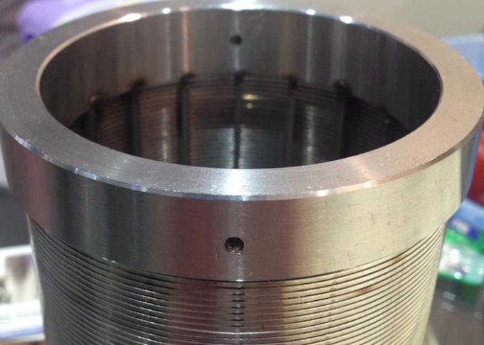
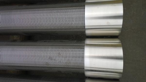
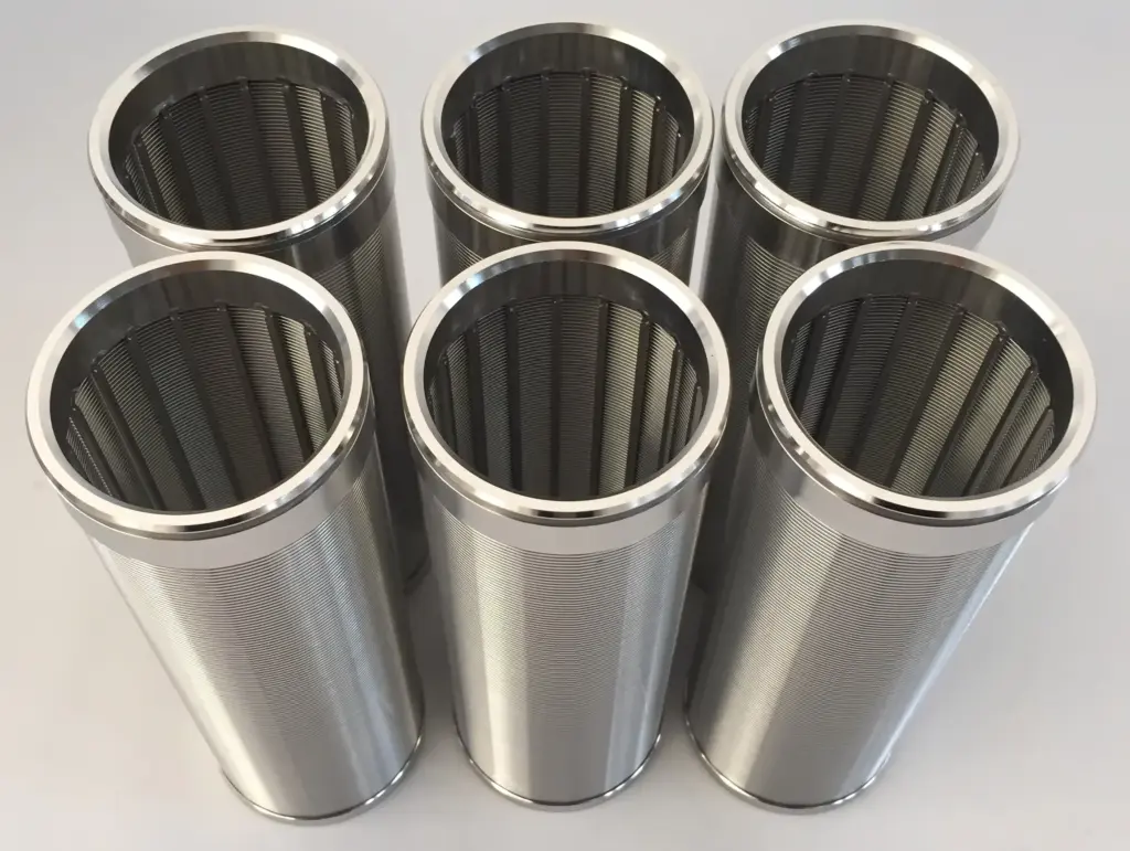
9. End Connection Mechanics & Joint Configurations
To safely install screens downhole, the end connection configurations must match the tension profiles of the deployment string. We engineer three primary joint termination configurations:
Plain Beveled Welding Rings
Designed for direct field-welded installations. Ends feature precise 30° or 37.5° weld bevel layouts, enabling smooth multi-pass manual arc or automated orbital TIG processing on-site.
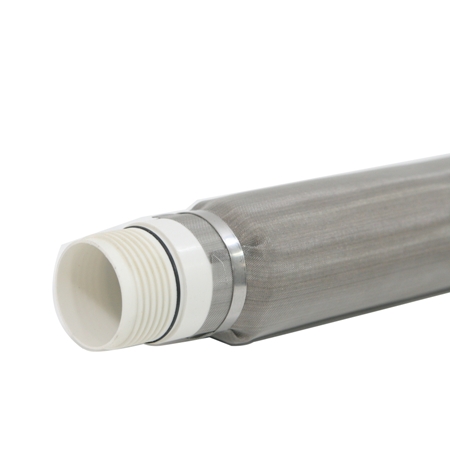
Threaded Couplings (Male / Female)
Precision machined using CNC equipment. Thread options include standard API STC/LTC casings, BTC buttress variants, or customized parallel metric thread tracks for tight clearance wells.
Bolted Companion Flanges
Engineered for fast integration with surface process vessels, processing plants, or industrial water intake systems. Built to strict corporate dimensions matching ASME B16.5, DIN, or JIS standards.
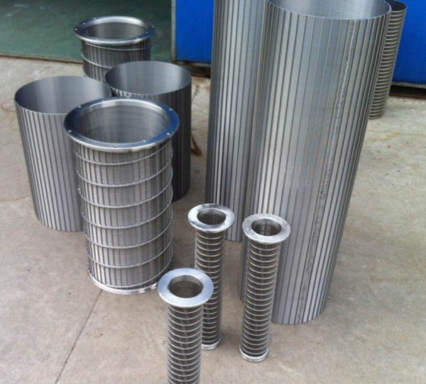
10. Specialized Product Configurations & Variations
Wedge wire geometry can be modified to serve varied processing requirements beyond standard water well deployment strings. The layout table below matches specific processing tasks with their specialized screen configurations:
| Product Configuration Name | Primary Process Application | Unique Engineering Feature |
|---|---|---|
| Wedge Wire Screen Cylinder | Rotary drum sifting, separation loops. | Continuous internal longitudinal support alignment. |
| Pressure Arc Screen for Starch | Corn/starch milling dewatering fields. | Curved profile plate optimizing material shear action. |
| Sieving Bending Screen Panels | Coal washing mud separation circuits. | High-efficiency gravitational slide geometry. |
| Wedge Wire Filter Nozzles | Ion exchange vessel distribution caps. | Compact threaded configurations with ultra-fine slots. |
| Pressure Screen Drum | Pulp and paper matrix processing. | Heavy exterior reinforcement bands for high-vibration environments. |
| Rotary Drum Screen Assemblies | Municipal wastewater intake screening. | Self-cleaning peripheral drive configuration. |
11. Quality Control Protocols & Non-Destructive Testing
Every structural production run undergoes systematic quality checks to confirm uniform slot accuracy and ensure downhole integrity. Our non-destructive testing framework includes:
- Microscopic Slot Dimension Auditing: Automated optical profile projectors check the slot opening width at 50mm length intervals to keep slot variance within ±0.015mm.
- Weld Joint Shear Strength Verification: Destructive physical tests confirm that the fusion strength at wire intersections exceeds the base metal tensile capacity.
- X-Ray Radiographic Examination (RT): Verifies full-penetration structural integrity across critical circumferential coupling weld lines.
- Hydrostatic Compression Testing: Subjects the filter tubes to target pressure differentials to verify design collapse values.
12. B2B International Procurement & Logistics Mapping
When sourcing custom-engineered **stainless steel wedge wire filters** for major infrastructure projects, buyers receive full material traceability compliance records. All shipments are packed in heavy internal wooden framework boxes wrapped with protective polymer layers to protect the slot edges from impact or warping during multi-modal ocean and rail transit routes.
Engineering Verification Reference Statement: All technical performance values, open area metrics, and collapse pressure limitations are derived from laboratory structural load testing loops and verified against DIN/AWWA well construction guidelines. Before specifying project dimensions, verify localized downhole formation constraints with your technical engineering representative.