
johnson continuous slot pipe based water well screens
November 17, 2017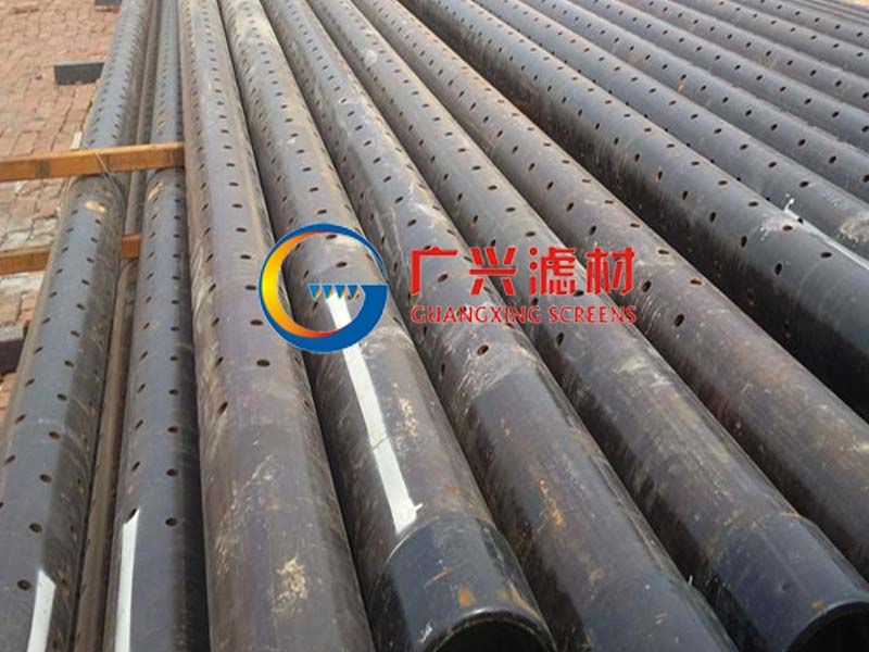
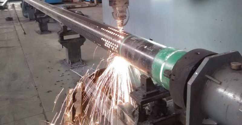
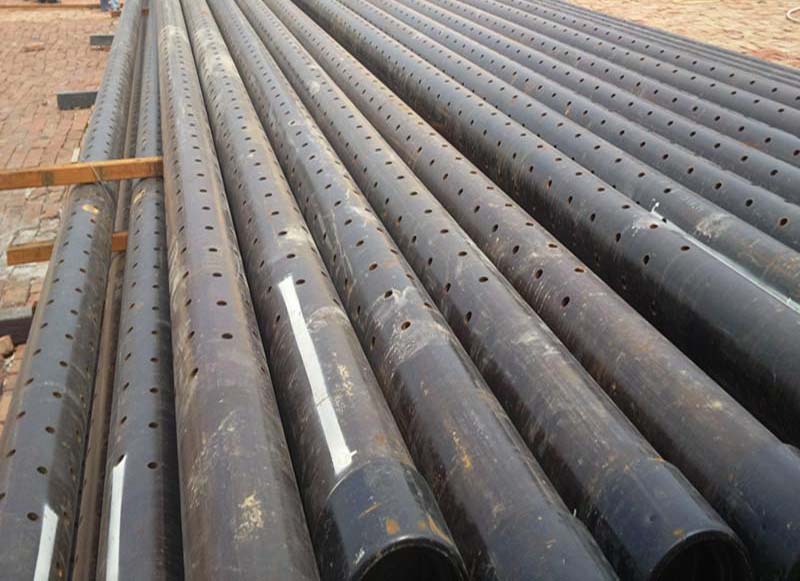
Perforated well casing and screen
November 23, 2017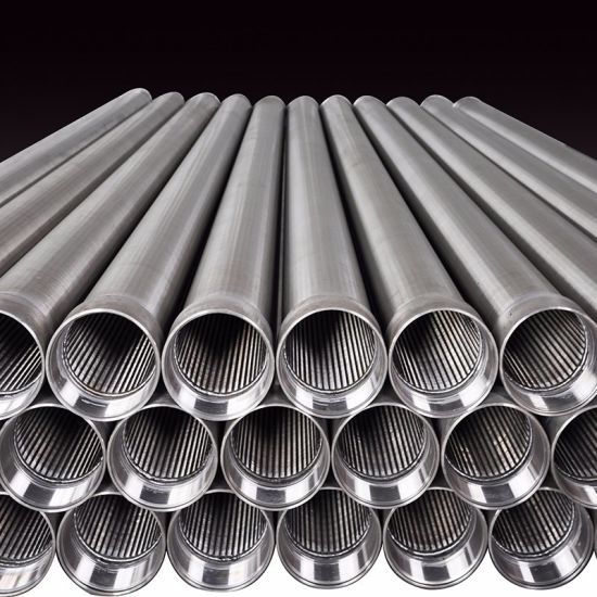
1. Well screen selection.
2. Drilling methodology.
3. Centralizing and annular packing.
4. Calibration of the meter.
5. Vector resolution.
6. Mapping the flow network.
KER FOOT ON WELL CONSTRUCTION
Initially, it is important to obtain basic field information concerning the geology of the site, the approximate depth to static water from grade, locations of any surface-water flows, such as rivers, tidal streams, or lakes, which may determine boundary conditions, and presence of withdrawal wells.
For unconsolidated deposits of sands and gravels, the nature of the soils and their particle size sets practical limits on the well slot size and probable location below grade for installation. Indirectly, the more heterogeneous the deposit and the larger the diameter of the screen, the more averaging of velocities and directions occurs because of the larger cross sectional area intercepted. Regions within known confined aquifers should be evaluated only with short screens and sealing to avoid vertical flow short-circuiting between water-bearing layers.
Well screens have previously been chosen from a practical standpoint by the well driller from what was closest at hand or from the most convenient distributor in the locale with the greatest discount. For direct flow measurement, far more care must be exercised in well screen selection to avoid distortion of field flow and to assure adequate flow rates across the screened area. The type of well screen can have considerable influence on the accuracy of the ground-water flow measurements performed inside the screen [4]. Installation of sections of pipe consisting of random hand-drilled rows of holes or intermittent horizontal hacksawing creates distortions of flow over 40 deg and potential 100-fold rate variations, depending upon whether the thermal sensor is opposite a hole or a blank space.
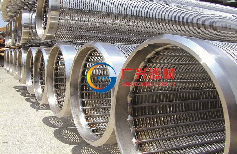
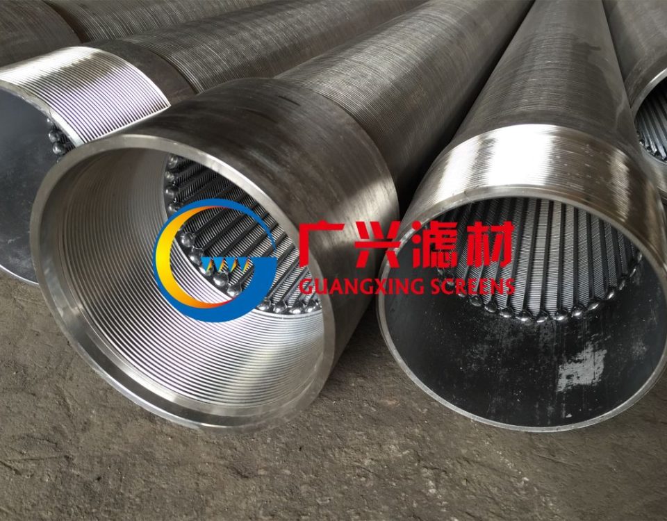
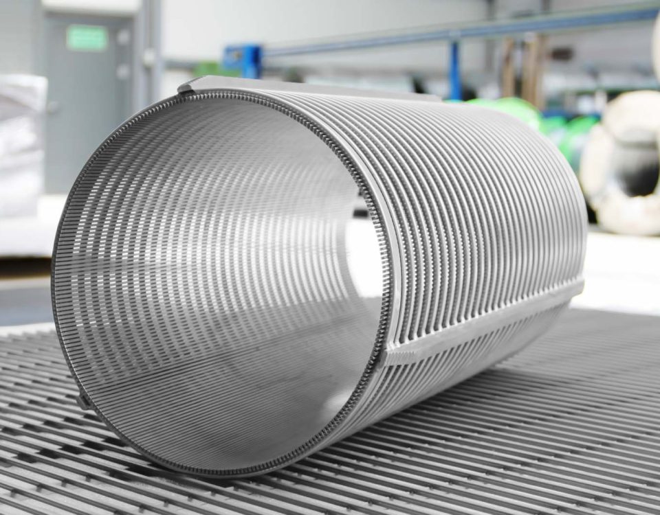
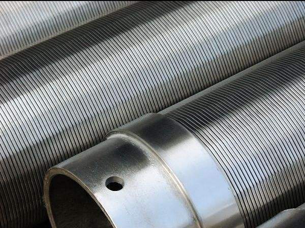
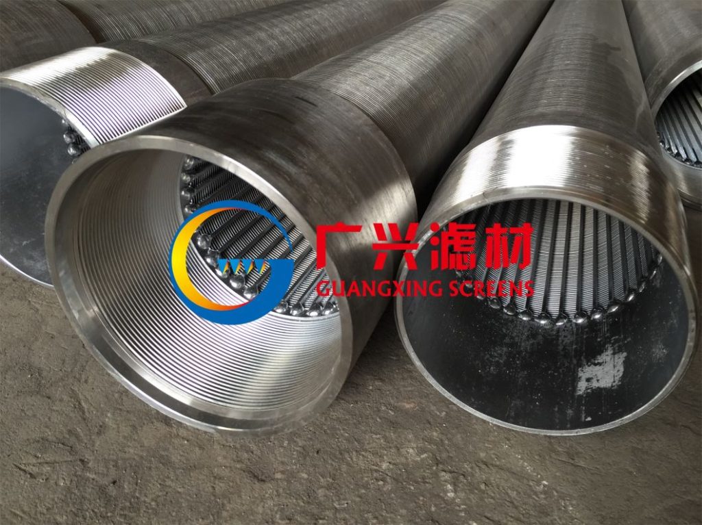
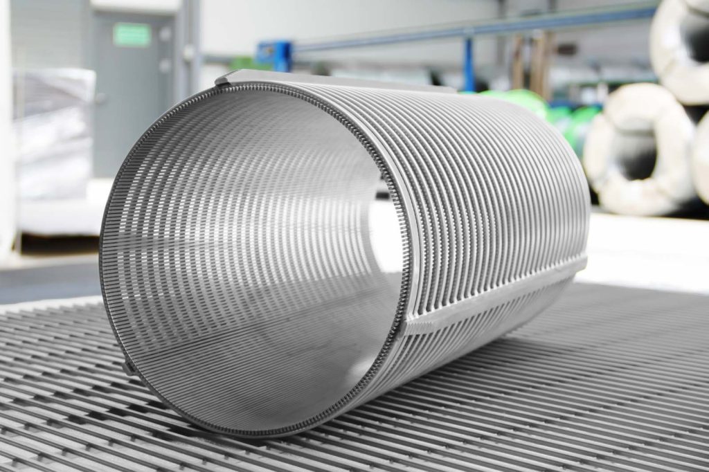
A variety of commercial smooth interior wire-wound, continuous slot plastic [polyvinyl chloride (PVC)] screens and stainless steel wire-wrapped screens has been found satisfactory for sensitive measurements (Fig. 2). The preferred diameters have been 5-cm (2 in.) and 10-cm (4 in.) internal diameter screens. Although probes and well screens exist for 3.8-cm (1.5 in.) PVC, the reduction in intercepted cross section is considered undesirable for flow direction determinations.
The commonly used 5-cm (2 in.) internal diameter schedule 40 ASTM plastic screens (PVC) should possess the following characteristics:
should possess the following characteristics:
1. Continuous slot.
2. Slot orientation: perpendicular to axis of casing.
3. Slot distance: 0.6 cm (0.25 in.) or less.
4. Slot rows: greater than 3 or continuous slot.
5. Rush jointing.
See Table 1 for some common commercial 5-cm (2 in.) PVC screens which fit these criteria.
The number of rows of slots in 5-cm (2 in.) internal diameter PVC monitoring wells has a significant influence on the accuracy of the ground-water flow direction, inferred from the interscreen direction \4], Figure 3 plots the accuracy of flow direction determinations inside the well relative to the true flow outside the well against the number of rows of slots. As the number of rows of slots increases, the accuracy of measurement increases markedly.
TABLE 1 —Characteristics of selected 4-cm (2 in.) ID, plastic monitoring well screens recommended for flowmeter use.
| Manufacturer | NSF Pipe Size | Screen
Gauge Slots Slot Size (in.) per ft Rows |
Inside
Diameter, in. |
Outside
Diameter, in. |
Wall
Thickness, in. |
Resis- Slot tance* Area (% flow) | |||
| Timcoc | Schedule 40 | 0.020 | 59 | 4 | 1.89 | 2.1 | 0.210 | 5.0 | 60% |
| Schedule 80 | 0.010 | 62 | 4 | 1.89 | 2.1 | 0.210 | 2.6 | 83% | |
| Died rich | Schedule 40 P-12 | 0.020 | 63 | 5 | 2.01 | 2.38 | 0.37 | 5.2 | 58% |
| Schedule 40 P-12 | 0.010 | 69 | 5 | 2.01 | 2.38 | 0.37 | 2.7 | 80% | |
| Johnson Well | continuous 2 in. | 0.020 | 79 | c | 1.939 | 2.375 | 0.218 | 5.8 | 32% |
| Screen” | |||||||||
| continuous 2 in. | 0.010 | 84 | c | 1.939 | 2.375 | 0.218 | 2.9 | 48% | |
| Johnson | continuous 2 ps | 0.020 | 78 | c | 1.875 | 2.375 | 0.220 | 10.2 | 29% |
| Screen’ | |||||||||
| continuous 2 ps | 0.010 | 82 | c | 1.875 | 2.375 | 0.220 | 6.8 | 45% | |
a This is not intended as a sole endorsement of the manufacturers listed. Other comparable commercial screens exist and can be evaluated by their characteristics.
b Resistance is measured at 3 m/day (10 ft/day) transport velocity in 15.24-cm (6 in.) ID flow chamber with medium sand external packing and 1 mm (0.039 in.) glass bead interval packing in fuzzy packer:
^ Unimpeded flow – flow through screen
t\ —=
Unimpeded flow
c ^Timco Geotechnical Products,Timco Manufacturing Co., Inc., P.O. Box 35, Prairie du Sac, WI 53578, 1983.
d ^Specifications Sheet,** Johnson Wei) Equipment, Inc., 9131 Highway 98 West, P.O. Box 3364, Pensacola, FL 32506, 1982.
e ^Johnson PVC Plastic Water Well Screens, Specification Sheet,*’ Johnson Division, United Oil Products, P.O. Box 43118, St. Paul, MN 55164, 1979.
,“Geotechnical Newsletter,” K-V Associates, Inc.,281 Main St.,Falmouth, MA 02540, Vol. 1,No. 1, 1980.
Conversion factors: 1 in. = 25.4 mm; 1 ft = 0.3048 m.
Interruptions in the continuous slotting create measurement and interpretation difficulties. Blank regions created by horizontal unslotted bars for strength cannot be distinguished from thin silt layers during readings in fluvial sand deposits. Similarly, vertical slotting in rows creates regions of rate change, reaching a maximum when the sensor is present at the center of the slotted region and reaching a minimum in the region of blank wall between the slots. While operationally some success has resulted by placing a nylon “tickler” or nailpoint on the end of an interval packer to ^sense** the position of blank walls during readings in shallow wells [1.5 to 12 m (5 to 40 ft)], these well screens are not desirable for direct flow measurements.
Slot thickness also has a pronounced influence on accuracy of flow rates. Figure 4 shows the relationship between well screen slot size and resistance to flow. Increasing slot size dramatically increases the volume of flow through the screen. It would be advisable to use a 0.5-mm (0.020 in.) slot screen with coarse sand annular packing to keep silt out rather than use a 0.15-mm (0.006 in.) slot if low flows [less than 3.5 x 10~6 m/s (1.0 ft/day)] are to be measured. As previously shown in Table 1, continuous slot well screen maintains the highest slot area per foot, roughly three times that of interval-slotted screen. In addition, increasing the diameter of the well screen increases the flow-through rate.
A 10-cm (4 in.) internal diameter well screen with six rows of slots and 0.5 mm (0.020 in.)
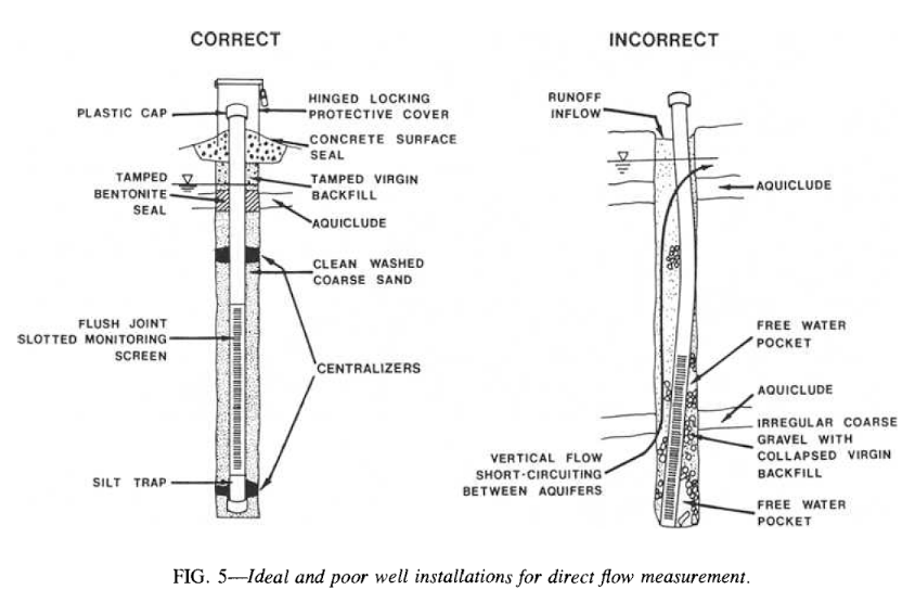
It is also important to centralize the causing. If the casing bends and positions the screen against the wall, it can shield the immediate region from the annular packing (Fig. 5). Several commercial centralizers are available, both solvent welded and metal. Avoiding channelization around the slotted casing is extremely important. Small channels along a section of the screened area can invalidate the instrument response.
The best strategy for confined aquifers has been similar to recommended methods for emplacement of piezometers: (a) Use limited screen length [1.5 to 3.0 m (5 to 10 ft) at maximum] between confining layers; (b) seal with bentonite at penetration points of casing through any confining layers; and (c) use clusters of individual screens rather than multiple screens on a single casing to avoid inducing vertical movement of water up casing between confining layers under different head pressures.
Calibration of the Meter
Ground-water flowmeters are equipped with a control box and field probe. The unit is powered by rechargeable gel-cell batteries. The field probe of the Model 30 GeoFlo meter is 4.44 cm (1.75 in.) in diameter, suitable for 5-cm (2 in.) slotted PVC monitoring wells.
Electronic ground-water flow measurement is based upon thermal transmission within a porous solid under the influence of interstitial liquid flow. The controlling factors are thermal conductance of the solid and liquid phases, surface area of the solid phase, thermal transfer coefficient of the liquid phase, and rate of movement of the liquid phase.
For example, with a porous solid phase of glass heads with distilled water, the thermal conductivity of the glass is about 0.023 cal/(s)(cm2)(°C/cm) while that of the water is 0.0015 cal/ (s)(cm2)(°C/cm). The principal heat transfer occurs between the zones of contact of the glass beads, a small point surrounded by a thin interface of water. The slightest movement of the liquid during the period of heat transfer can profoundly influence the conductance. The GeoFlo flowmeter creates a heat pulse which is transmitted through the porous matrix. Any net movement of the interstitial water mass creates a thermal conductance bias which is linearly proportional to the rate of flow (Fig. 6).

