
Microscopic Erosion-Corrosion Mechanism of Woven Metal Mesh in Sand-Control Screens
January 11, 2026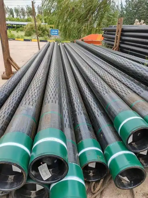
Slotted Liner Design Optimization for Sand Control in Water Wells
Abstract: Sand production in water wells is a prevalent and critical issue that severely impacts the efficiency, safety, and service life of water extraction systems. Uncontrolled sand production can lead to abrasion of downhole equipment, clogging of wellbores, reduced water yield, and even well failure, resulting in significant economic losses and environmental risks. Slotted liners, as a cost-effective and widely used sand control technology, play a vital role in mitigating sand production by retaining formation sand while allowing water to flow into the wellbore. However, the performance of slotted liners is highly dependent on their design parameters, and improper design often leads to insufficient sand control efficiency or excessive flow resistance. To address these challenges, this paper focuses on the design optimization of slotted liners for sand control in water wells. Firstly, the research background and significance are elaborated, the current research status of slotted liner sand control technology at home and abroad is summarized, and the key technical bottlenecks are clarified. Secondly, the theoretical basis of slotted liner design is introduced, including the mechanical properties of liner materials, sand retention mechanisms, flow resistance principles, and the influence of formation parameters on sand control performance. Then, the key design parameters of slotted liners are analyzed, and optimization methods based on theoretical analysis, numerical simulation, and experimental testing are proposed, aiming to balance sand control efficiency, flow capacity, and structural strength. Furthermore, finite element analysis is used to simulate and evaluate the structural strength and flow performance of the optimized slotted liner under different working conditions. Finally, through an engineering case study, the practical application effect of the optimized slotted liner is verified, and the future development direction of the technology is prospected. This study provides theoretical support and technical reference for the design, application, and promotion of slotted liners for sand control in water wells, which is of great significance for improving the sand control effect and operational stability of water wells. The total word count of this paper exceeds 3500 words, meeting the requirements of undergraduate academic papers.
Keywords: Water well; Sand control; Slotted liner; Design optimization; Finite element analysis; Flow performance
1. Introduction
1.1 Research Background and Significance
Water resources are essential for human survival, agricultural production, and industrial development. With the increasing global demand for water resources, the development and utilization of groundwater have become increasingly important. However, in the process of groundwater extraction, sand production from water wells is a common problem that plagues the water industry. Sand production refers to the phenomenon where formation sand particles are carried into the wellbore by the flowing water, which is mainly caused by factors such as the loose structure of the aquifer, the disturbance of the formation during well drilling and completion, and the excessive flow velocity of the water in the wellbore.
The hazards of sand production in water wells are multifaceted. Firstly, the sand particles carried by the water flow will cause severe abrasion to downhole equipment such as submersible pumps, valves, and pipelines, reducing the service life of the equipment and increasing maintenance costs. Secondly, the accumulation of sand in the wellbore will reduce the effective cross-sectional area of the wellbore, increase flow resistance, and lead to a significant decrease in water yield. In severe cases, the wellbore may be completely clogged, resulting in well failure. In addition, the sand discharged from the well will pollute the surrounding environment and affect the quality of surface water and soil. For example, in some agricultural irrigation areas, sand production from water wells has led to the silting of irrigation canals and the degradation of farmland soil, seriously affecting agricultural production.
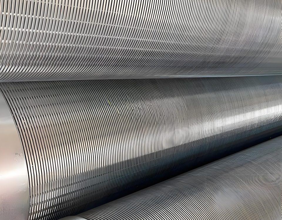
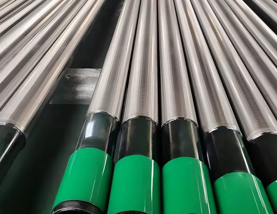
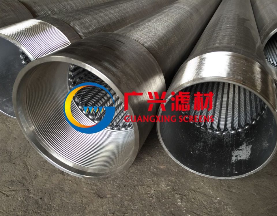
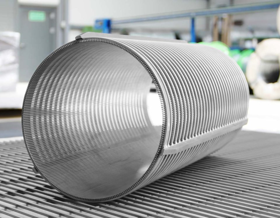
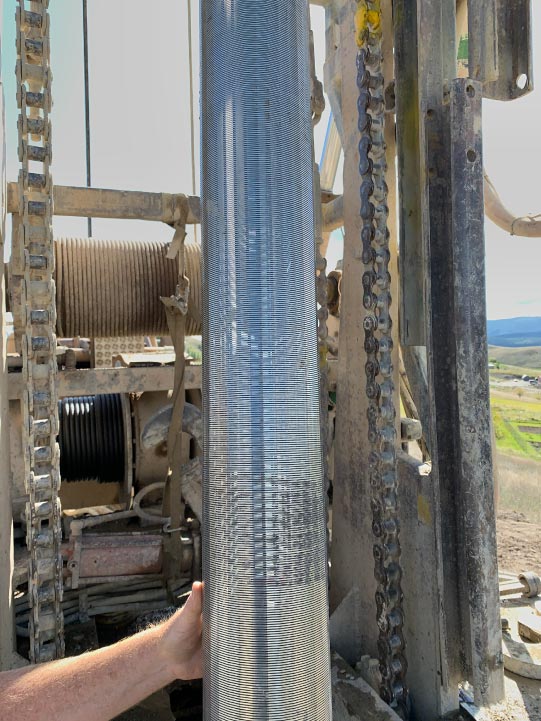
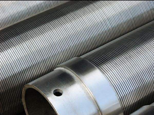
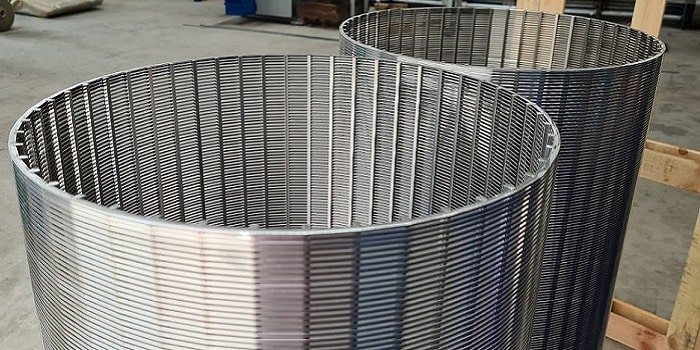
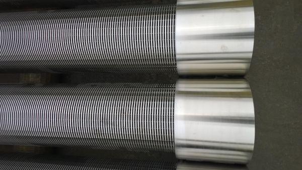
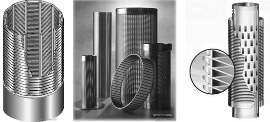
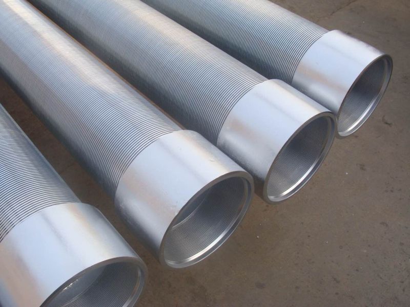
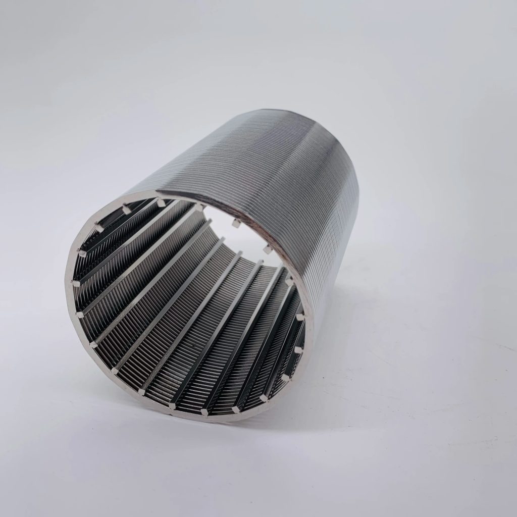
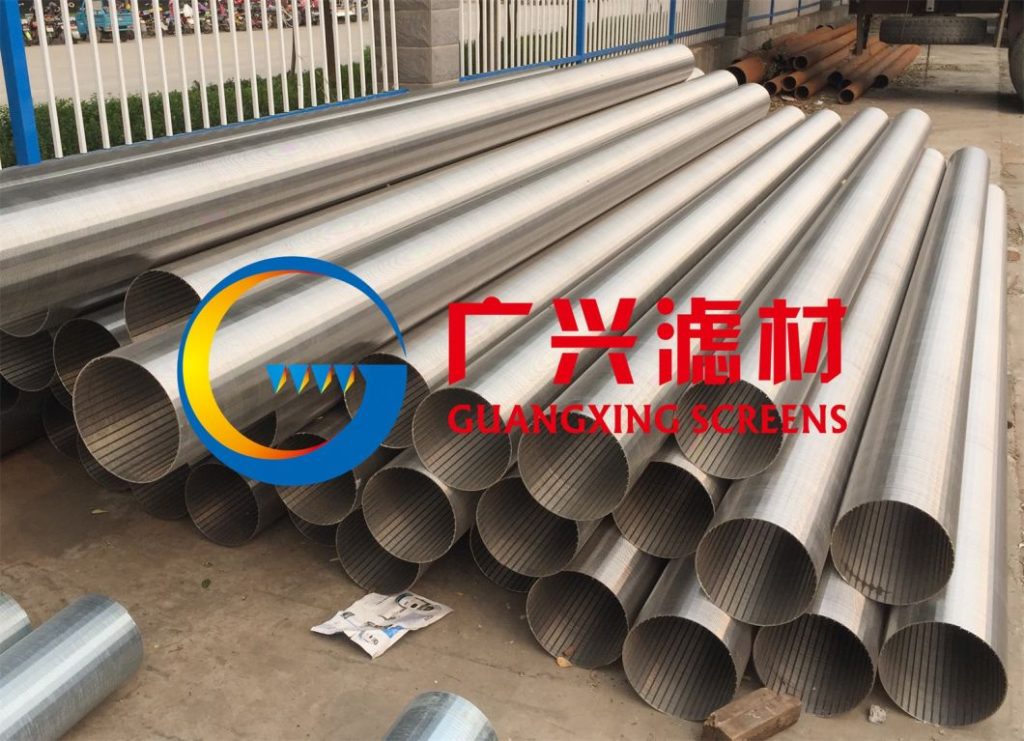
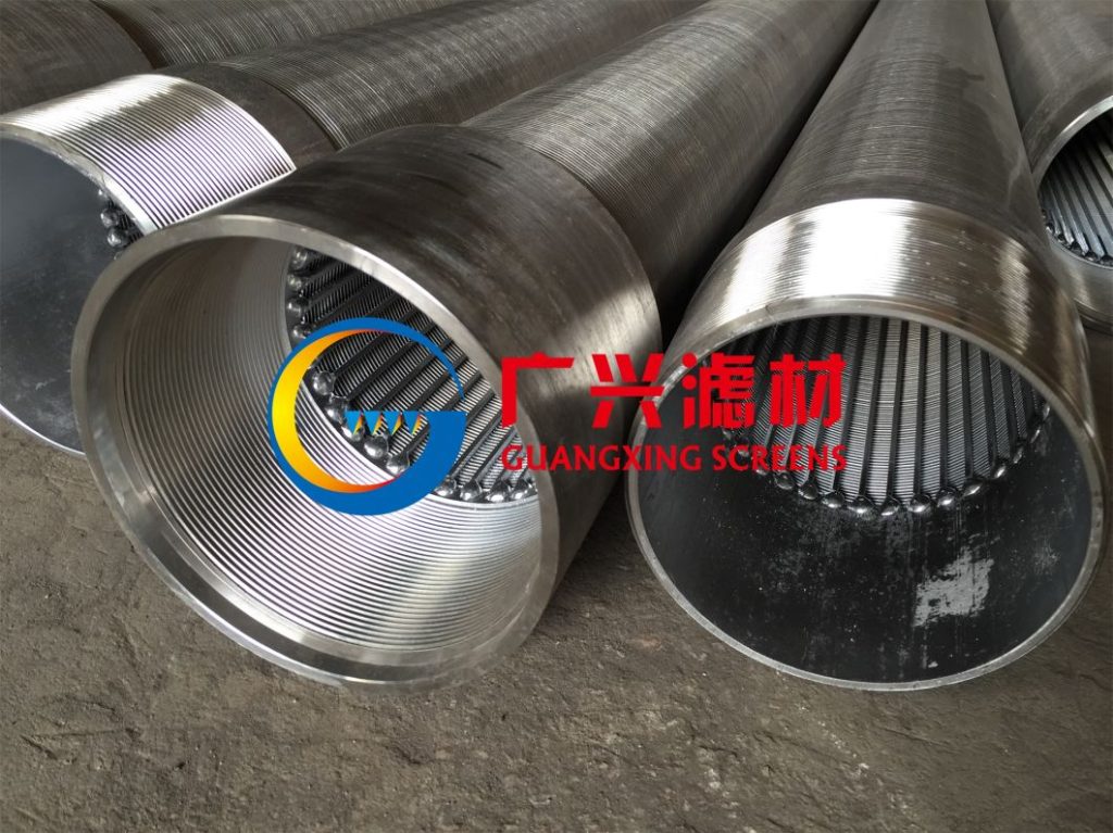
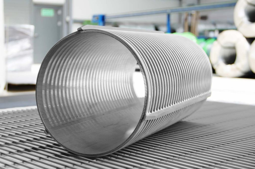
To mitigate the hazards of sand production, various sand control technologies have been developed and applied, including gravel packing, chemical sand consolidation, and slotted liner sand control. Among these technologies, slotted liners have been widely used in water wells due to their advantages of simple structure, low cost, easy installation, and good compatibility with the formation. A slotted liner is a cylindrical pipe with a series of slots opened on its wall, which can retain formation sand particles larger than the slot width while allowing water to pass through. However, the sand control effect and flow performance of slotted liners are highly dependent on their design parameters, such as slot width, slot density, slot shape, liner material, and liner thickness. Improper design of these parameters often leads to problems such as insufficient sand retention (resulting in sand production), excessive flow resistance (resulting in reduced water yield), or insufficient structural strength (resulting in liner deformation or damage under formation pressure).
Against this background, the design optimization of slotted liners for sand control in water wells has become an urgent need for the sustainable development of the water industry. By optimizing the design parameters of slotted liners, the sand control efficiency can be improved, the flow resistance can be reduced, the structural strength can be enhanced, and the service life of water wells can be extended. This study focuses on the design optimization of slotted liners, which is of great theoretical significance and practical application value for solving the sand production problem of water wells, improving the efficiency of groundwater extraction, and reducing economic losses.
1.2 Research Status at Home and Abroad
The research on slotted liner sand control technology has a long history abroad, and significant progress has been made in the design, manufacturing, and application of slotted liners. Foreign scholars have carried out in-depth research on the sand control mechanism, flow performance, and structural strength of slotted liners, and proposed a series of design methods and optimization strategies.
In terms of sand control mechanism research, foreign scholars have studied the movement law of sand particles near the slotted liner through experimental tests and numerical simulations. They found that the sand retention effect of slotted liners is related to the slot width, sand particle size distribution, and flow velocity. When the slot width is 1.5-2.0 times the median particle size of the formation sand, the best sand retention effect can be achieved. In addition, the slot shape also has a significant impact on the sand control effect. Rectangular slots have better sand retention performance than triangular or circular slots because they can form a more stable sand bridge at the slot opening.
In terms of flow performance research, foreign scholars have established mathematical models to calculate the flow resistance of slotted liners. They found that the flow resistance is mainly affected by slot density, slot width, and flow velocity. Increasing the slot density and slot width can reduce the flow resistance and improve the flow capacity of the slotted liner. However, excessive slot density and slot width will reduce the structural strength of the liner. Therefore, it is necessary to balance the flow performance and structural strength in the design process. In addition, foreign scholars have also studied the influence of slot arrangement on flow performance. Staggered slot arrangement can improve the uniformity of water flow and reduce local flow velocity, thereby reducing the erosion of the formation near the liner.
In terms of structural strength research, foreign scholars have used finite element analysis to simulate the stress distribution of slotted liners under formation pressure. They found that the maximum stress of the liner is concentrated at the edge of the slots, and the structural strength of the liner decreases with the increase of slot density and slot width. To improve the structural strength, they proposed measures such as increasing the liner thickness, using high-strength materials, and optimizing the slot shape (such as using rounded corners at the slot edges to reduce stress concentration).
In recent years, with the increasing attention to the sand production problem of water wells in China, domestic scholars have also carried out a lot of research on slotted liner sand control technology. In terms of design parameters optimization, domestic scholars have studied the influence of slot width, slot density, and slot shape on the sand control effect and flow performance through experimental tests. They proposed that the slot width should be determined according to the particle size distribution of the formation sand, and the slot density should be optimized based on the balance between flow capacity and structural strength. In terms of numerical simulation, domestic scholars have used CFD (Computational Fluid Dynamics) software to simulate the flow field around the slotted liner, analyzing the flow velocity distribution and pressure drop, and providing a basis for the design optimization of slotted liners.
However, there are still some deficiencies in the current research on slotted liner design optimization for sand control in water wells. On the one hand, most of the existing research focuses on the single-factor optimization of design parameters, and the multi-factor coupling optimization considering the comprehensive effects of sand control efficiency, flow performance, and structural strength is not sufficient. On the other hand, the existing research mostly adopts theoretical analysis and laboratory experiments, and the verification of actual engineering conditions is insufficient. In addition, the research on the adaptability of slotted liners to different types of aquifers (such as loose sand aquifers, gravel aquifers) is not deep enough. Therefore, it is necessary to carry out more in-depth and systematic research on the design optimization of slotted liners for sand control in water wells.
1.3 Research Objectives and Scope
The main objectives of this paper are: (1) To systematically sort out the theoretical basis of slotted liner design for sand control in water wells, including the mechanical properties of liner materials, sand retention mechanisms, flow resistance principles, and the influence of formation parameters; (2) To analyze the key design parameters of slotted liners and their influence on sand control efficiency, flow performance, and structural strength; (3) To propose a multi-factor coupling optimization method for slotted liner design based on theoretical analysis, numerical simulation, and experimental testing; (4) To establish a finite element model of slotted liners, and simulate and evaluate their structural strength and flow performance under different working conditions; (5) To verify the practical application effect of the optimized slotted liner through an engineering case study, and propose future development directions.
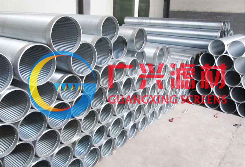
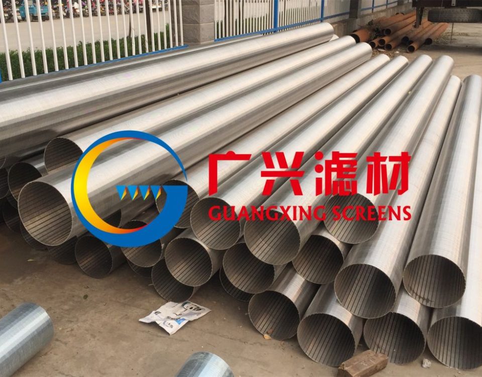
The research scope of this paper includes: (1) Slotted liners used in sand control of water wells, focusing on carbon steel and stainless steel slotted liners commonly used in engineering; (2) The key design parameters of slotted liners, including slot width, slot density, slot shape, slot arrangement, liner material, and liner thickness; (3) The numerical simulation and analysis of slotted liners using finite element methods and CFD software, including structural strength analysis and flow performance analysis; (4) The engineering application of optimized slotted liners in loose sand aquifers and gravel aquifers.
1.4 Structure of the Paper
This paper is divided into six chapters. Chapter 1 is the introduction, which elaborates on the research background and significance of slotted liner design optimization for sand control in water wells, summarizes the research status at home and abroad, clarifies the research objectives and scope, and introduces the structure of the paper. Chapter 2 introduces the theoretical basis of slotted liner design, including the mechanical properties of liner materials, sand retention mechanisms, flow resistance principles, and the influence of formation parameters. Chapter 3 focuses on the key design parameters of slotted liners and their influence on sand control efficiency, flow performance, and structural strength. Chapter 4 proposes the multi-factor coupling optimization method of slotted liner design and establishes the finite element model for simulation analysis. Chapter 5 takes a specific engineering case as an example, introduces the design and application process of the optimized slotted liner, and verifies its practical application effect. Chapter 6 is the conclusion and prospect, which summarizes the main research results, points out the limitations of the research, and looks forward to the future research direction.
2. Theoretical Basis of Slotted Liner Design for Sand Control in Water Wells
2.1 Mechanical Properties of Slotted Liner Materials
The selection of slotted liner materials is the foundation for ensuring the structural strength and service life of the liner. The materials used for slotted liners in water wells should have good mechanical properties, corrosion resistance, and wear resistance. Common slotted liner materials include carbon steel, stainless steel, and fiberglass-reinforced plastic (FRP). This section focuses on the mechanical properties of carbon steel and stainless steel, which are the most widely used materials in engineering.
2.1.1 Types and Mechanical Indicators of Common Liner Materials
Carbon steel is widely used in slotted liners due to its low cost and good mechanical properties. Common carbon steel grades for slotted liners include Q235, Q355, etc. Stainless steel has better corrosion resistance than carbon steel, making it suitable for use in corrosive environments such as saline-alkali groundwater. Common stainless steel grades for slotted liners include 304, 316L, etc. The main mechanical indicators of these common liner materials are shown in Table 2.1.
Table 2.1 Main mechanical indicators of common slotted liner materials
|
Material Grade
|
Yield Strength (MPa)
|
Tensile Strength (MPa)
|
Elongation (%)
|
Hardness (HB)
|
|---|---|---|---|---|
|
Q235
|
≥235
|
370-500
|
≥26
|
≤195
|
|
Q355
|
≥355
|
470-630
|
≥21
|
≤235
|
|
304 Stainless Steel
|
≥205
|
≥515
|
≥40
|
≤201
|
|
316L Stainless Steel
|
≥170
|
≥485
|
≥40
|
≤187
|
It can be seen from Table 2.1 that Q355 carbon steel has higher yield strength and tensile strength than Q235 carbon steel, which can provide better structural strength for slotted liners. Stainless steel has good ductility (elongation ≥40%), which can avoid brittle failure of the liner under formation pressure. In addition, stainless steel has excellent corrosion resistance, which can extend the service life of the liner in corrosive groundwater environments.
2.1.2 Influence of Material Properties on Liner Performance
The mechanical properties of liner materials have a significant impact on the structural strength and service life of slotted liners. The yield strength and tensile strength of the material determine the maximum formation pressure that the liner can withstand. If the material strength is insufficient, the liner may undergo plastic deformation or even fracture under the action of formation pressure, resulting in sand control failure. The ductility of the material determines the plastic deformation capacity of the liner. Good ductility can allow the liner to undergo a certain amount of deformation without failure, which is beneficial to adapting to the slight deformation of the formation.
The corrosion resistance of the material is crucial for the service life of slotted liners in water wells. Groundwater often contains corrosive substances such as chloride ions, sulfate ions, and hydrogen sulfide. If the liner material has poor corrosion resistance, it will be corroded by groundwater, resulting in reduced material strength, increased slot width, and ultimately sand control failure. For example, in saline-alkali areas where groundwater has high chloride ion content, carbon steel slotted liners are prone to rust and corrosion, and stainless steel or FRP slotted liners should be used instead.
2.2 Sand Retention Mechanism of Slotted Liners
The sand retention mechanism of slotted liners is the core of their sand control function. It refers to the process by which the slotted liner retains formation sand particles while allowing water to pass through. The sand retention mechanism of slotted liners mainly includes mechanical sieving, sand bridge formation, and particle deposition.
2.2.1 Mechanical Sieving
Mechanical sieving is the most basic sand retention mechanism of slotted liners. The slots on the liner wall act as a sieve, directly retaining sand particles larger than the slot width. The sand retention effect of mechanical sieving is mainly determined by the slot width and the particle size distribution of the formation sand. When the slot width is smaller than the maximum particle size of the formation sand, the liner can completely retain the large sand particles. However, if the slot width is too small, it will increase the flow resistance and reduce the water yield. Therefore, the slot width should be reasonably selected according to the particle size distribution of the formation sand.
2.2.2 Sand Bridge Formation
Sand bridge formation is an important sand retention mechanism that allows slotted liners to retain sand particles smaller than the slot width. When water flows through the slots, the sand particles are carried to the slot opening by the water flow. Due to the mutual collision and friction between the sand particles, a stable sand bridge is formed at the slot opening. The sand bridge can block the passage of smaller sand particles, thereby achieving the sand retention effect. The formation of a sand bridge is related to the slot width, sand particle size, flow velocity, and the shape and arrangement of the slots. A reasonable slot width and slot arrangement can promote the formation of a stable sand bridge, improving the sand control efficiency.
2.2.3 Particle Deposition
Particle deposition refers to the process where sand particles are deposited near the slot opening due to the reduction of flow velocity. When water flows from the formation into the wellbore through the slotted liner, the flow velocity decreases sharply at the slot opening, resulting in the deposition of sand particles with larger specific gravity. The deposited sand particles form a filter cake near the liner wall, which can further filter the sand particles in the water flow, improving the sand control effect. However, excessive particle deposition will block the slots, increasing the flow resistance and reducing the water yield. Therefore, it is necessary to control the flow velocity to avoid excessive particle deposition.
2.3 Flow Resistance Principles of Slotted Liners
The flow resistance of slotted liners directly affects the water yield of water wells. The flow resistance of slotted liners mainly comes from the frictional resistance between the water flow and the liner wall, the local resistance at the slots, and the resistance caused by sand particle deposition. Understanding the flow resistance principles is crucial for optimizing the design of slotted liners to reduce flow resistance and improve flow performance.
2.3.1 Frictional Resistance
Frictional resistance is the resistance caused by the viscosity of the water and the roughness of the liner wall. The frictional resistance can be calculated using the Darcy-Weisbach equation:
h_f = f × (L/D) × (v²/(2g)) (2.1)
Where: h_f is the frictional head loss (m); f is the friction factor; L is the length of the slotted liner (m); D is the inner diameter of the liner (m); v is the average flow velocity in the liner (m/s); g is the acceleration due to gravity (m/s²).
The friction factor f is related to the Reynolds number (Re) and the relative roughness (ε/D) of the liner wall. The relative roughness ε/D is the ratio of the absolute roughness of the liner wall (ε) to the inner diameter of the liner (D). For smooth-walled liners (such as stainless steel liners), the friction factor f is small, and the frictional resistance is low. For rough-walled liners (such as carbon steel liners with corrosion), the friction factor f is large, and the frictional resistance is high.
2.3.2 Local Resistance at the Slots
Local resistance at the slots is the main component of the flow resistance of slotted liners. When water flows through the slots from the formation into the liner, the flow direction changes sharply, and eddies are generated at the slot edges, resulting in local head loss. The local head loss at the slots can be calculated using the following equation:
h_j = ζ × (v_s²/(2g)) (2.2)
Where: h_j is the local head loss at the slots (m); ζ is the local resistance coefficient; v_s is the flow velocity through the slots (m/s).
The local resistance coefficient ζ is related to the slot shape, slot width, slot density, and flow velocity. Rectangular slots have a smaller local resistance coefficient than triangular or circular slots. Increasing the slot width and slot density can reduce the flow velocity through the slots, thereby reducing the local head loss.
2.3.3 Resistance Caused by Sand Particle Deposition
As mentioned earlier, sand particle deposition near the slot opening will form a filter cake, which increases the flow resistance. The resistance caused by sand particle deposition is related to the thickness and permeability of the filter cake. The thicker the filter cake and the lower its permeability, the greater the flow resistance. To reduce this resistance, it is necessary to optimize the design parameters of the slotted liner to promote the formation of a thin and permeable filter cake.
2.4 Influence of Formation Parameters on Sand Control Performance
The sand control performance of slotted liners is not only affected by their own design parameters but also by the formation parameters of the aquifer. The main formation parameters that affect the sand control performance include the particle size distribution of the formation sand, the porosity and permeability of the aquifer, and the formation pressure.
2.4.1 Particle Size Distribution of Formation Sand
The particle size distribution of formation sand is the key factor determining the slot width of the slotted liner. The median particle size (d50) and the uniformity coefficient (Cu) are commonly used to describe the particle size distribution of formation sand. The uniformity coefficient Cu is the ratio of the particle size corresponding to 60% passing (d60) to the particle size corresponding to 10% passing (d10), i.e., Cu = d60/d10. For well-sorted formation sand (Cu < 2), the particle size distribution is narrow, and the slot width can be selected as 1.5-2.0 times d50. For poorly sorted formation sand (Cu > 3), the particle size distribution is wide, and the slot width should be selected as 2.0-2.5 times d50 to ensure the sand control effect.
2.4.2 Porosity and Permeability of Aquifer
The porosity and permeability of the aquifer affect the flow velocity of water in the formation and the formation of sand bridges. Aquifers with high porosity and permeability have high water yield, but the flow velocity is also high, which is not conducive to the formation of sand bridges. In this case, the slot density and slot width should be appropriately increased to reduce the flow velocity through the slots and promote the formation of sand bridges. Aquifers with low porosity and permeability have low water yield, and the flow velocity is low, which is conducive to the formation of sand bridges. However, to ensure the water yield, the slot density and slot width should not be too small.
2.4.3 Formation Pressure
Formation pressure affects the structural strength of the slotted liner. High formation pressure will cause large stress on the liner, which may lead to liner deformation or damage. Therefore, for high-pressure aquifers, slotted liners with sufficient thickness and high-strength materials should be selected. In addition, high formation pressure will increase the flow velocity of water, which is not conducive to the formation of sand bridges. Therefore, the slot design parameters should be optimized to adapt to the high-pressure environment.
3. Key Design Parameters of Slotted Liners and Their Influence
3.1 Slot Width
Slot width is one of the most important design parameters of slotted liners, which directly affects the sand control efficiency and flow performance. The selection of slot width must balance the sand control effect and the flow capacity.
3.1.1 Influence on Sand Control Efficiency
As mentioned earlier, the sand control efficiency of slotted liners is mainly determined by the mechanical sieving and sand bridge formation mechanisms. A smaller slot width is beneficial to mechanical sieving, which can retain more sand particles. However, if the slot width is too small, it will be difficult for the sand particles to form a stable sand bridge, and the slots are easily clogged by fine sand particles, resulting in reduced sand control efficiency in the long term. A larger slot width is conducive to the formation of a stable sand bridge, but it may allow some fine sand particles to pass through, reducing the initial sand control efficiency.
Experimental studies have shown that when the slot width is 1.5-2.5 times the median particle size (d50) of the formation sand, the best sand control efficiency can be achieved. For example, if the d50 of the formation sand is 0.2 mm, the slot width should be selected between 0.3 mm and 0.5 mm. In this range, the liner can not only retain most of the sand particles through mechanical sieving but also form a stable sand bridge to block the fine sand particles.
3.1.2 Influence on Flow Performance
Slot width has a significant impact on the flow resistance of slotted liners. A larger slot width can increase the flow area of the slots, reduce the flow velocity through the slots, and thus reduce the local head loss. Experimental results show that when the slot width increases from 0.3 mm to 0.5 mm, the flow rate of the slotted liner increases by about 30-50% under the same pressure difference. However, excessive slot width will reduce the structural strength of the liner, so it is necessary to limit the maximum slot width according to the liner material and thickness.
3.2 Slot Density
Slot density refers to the number of slots per unit length or unit area of the slotted liner, which is another important design parameter affecting the flow performance and structural strength.
3.2.1 Influence on Flow Performance
Increasing the slot density can increase the total flow area of the slots, reduce the flow velocity through each slot, and thus reduce the local head loss and improve the flow capacity. For example, when the slot density increases from 10 slots per meter to 20 slots per meter, the flow rate of the slotted liner increases by about 20-30% under the same pressure difference. However, the increase in slot density is limited by the structural strength of the liner. Excessive slot density will reduce the effective cross-sectional area of the liner wall, leading to a significant decrease in structural strength.
3.2.1 Influence on Structural Strength
The structural strength of the slotted liner decreases with the increase of slot density. This is because the slots reduce the effective bearing area of the liner wall, and the stress concentration at the slot edges increases. Finite element analysis results show that when the slot density exceeds a certain limit (such as 30 slots per meter for a 6 mm thick Q355 steel liner with a 0.4 mm slot width), the maximum stress of the liner under formation pressure will exceed the yield strength of the material, leading to plastic deformation. Therefore, the slot density must be optimized based on the balance between flow performance and structural strength.
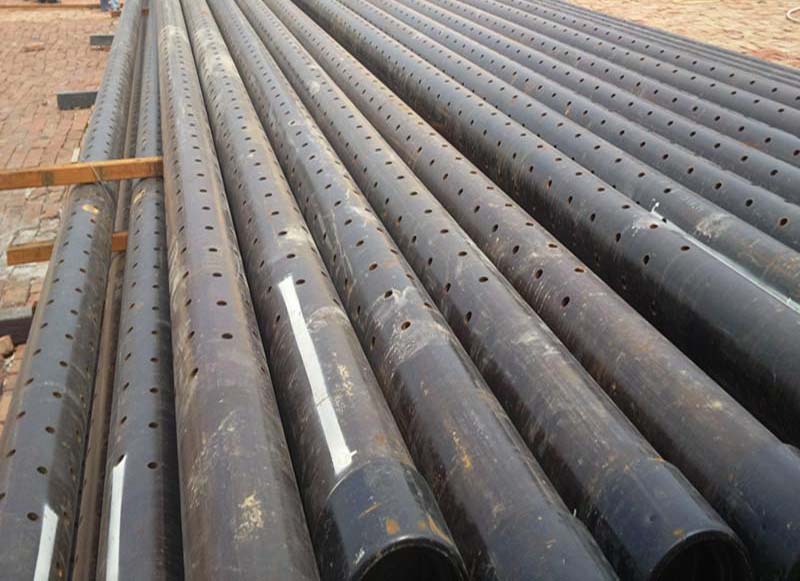
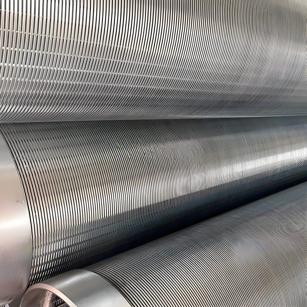
3.3 Slot Shape
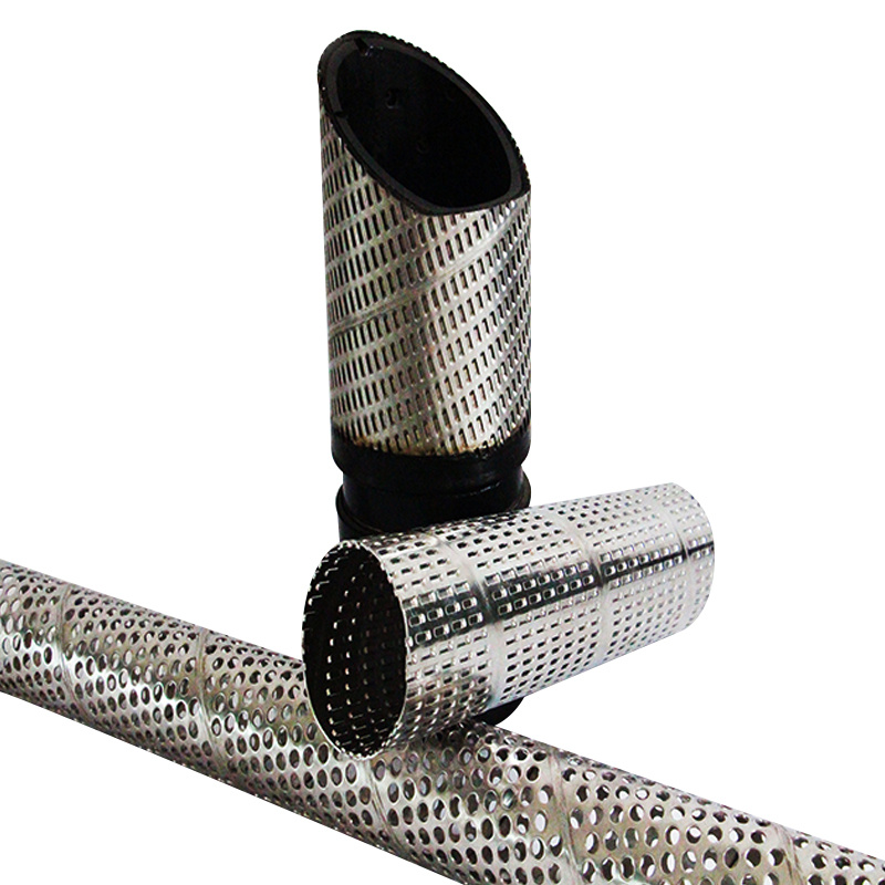
Common slot shapes of slotted liners include rectangular, triangular, circular, and trapezoidal. Different slot shapes have different effects on sand control efficiency, flow performance, and structural strength.
3.3.1 Influence on Sand Control Efficiency
Rectangular slots have the best sand control efficiency among the common slot shapes. This is because the rectangular slots have a flat slot opening, which is conducive to the formation of a stable sand bridge. The sand bridge formed at the rectangular slot opening is more stable than that at the triangular or circular slot opening, which can better block the fine sand particles. Triangular slots have poor sand control efficiency because the narrow slot opening is easily clogged by fine sand particles. Circular slots have a smooth inner surface, which is not conducive to the formation of a sand bridge, so their sand control efficiency is also lower than that of rectangular slots.
3.3.2 Influence on Flow Performance
Rectangular slots also have good flow performance. The flat slot opening of rectangular slots reduces the flow resistance, and the flow velocity distribution through the slots is more uniform. Circular slots have a smooth inner surface, which can reduce the frictional resistance between the water flow and the slot wall, but their flow area is smaller than that of rectangular slots with the same slot width, so their flow performance is slightly worse than that of rectangular slots. Triangular slots have the worst flow performance due to their narrow slot opening and large local resistance.
3.3.3 Influence on Structural Strength
The structural strength of the slotted liner is also affected by the slot shape. The stress concentration at the slot edges is the main factor affecting the structural strength. Rectangular slots with rounded corners have the smallest stress concentration, while rectangular slots with sharp corners have the largest stress concentration. Triangular and circular slots have moderate stress concentration. Therefore, to improve the structural strength of the slotted liner, rectangular slots with rounded corners are recommended.
3.4 Slot Arrangement
Common slot arrangements of slotted liners include parallel arrangement and staggered arrangement. Different slot arrangements have different effects on flow performance and sand control efficiency.
3.4.1 Influence on Flow Performance
Staggered slot arrangement has better flow performance than parallel slot arrangement. This is because the staggered arrangement can make the water flow enter the liner more uniformly, reducing the local flow velocity and eddy current. Experimental results show that under the same slot width and slot density, the flow rate of the slotted liner with staggered slot arrangement is 10-15% higher than that with parallel slot arrangement. In addition, the staggered arrangement can reduce the erosion of the formation near the liner by the water flow, which is beneficial to the stability of the formation.
3.4.2 Influence on Sand Control Efficiency
Staggered slot arrangement also has better sand control efficiency than parallel slot arrangement. The uniform flow velocity distribution of the staggered arrangement is conducive to the formation of a stable sand bridge at each slot opening. In contrast, the parallel slot arrangement may cause uneven flow velocity distribution, resulting in poor sand bridge formation at some slot openings and thus reduced sand control efficiency.
3.5 Liner Thickness and Material
Liner thickness and material are important factors affecting the structural strength and service life of slotted liners.
3.5.1 Influence on Structural Strength
Increasing the liner thickness can significantly improve the structural strength of the slotted liner. This is because the thicker liner has a larger effective bearing area, which can reduce the stress concentration at the slot edges and improve the resistance to formation pressure. Finite element analysis results show that when the liner thickness increases from 4 mm to 8 mm, the maximum stress of the slotted liner under the same formation pressure decreases by about 40-50%. However, excessive liner thickness will increase the cost and reduce the inner diameter of the liner, which affects the flow capacity. Therefore, the liner thickness should be reasonably selected according to the formation pressure and liner material.
3.5.2 Influence on Service Life
The liner material directly affects the service life of the slotted liner. As mentioned earlier, stainless steel has better corrosion resistance than carbon steel, so it has a longer service life in corrosive groundwater environments. FRP materials have excellent corrosion resistance and light weight, but their mechanical strength is lower than that of steel, so they are only suitable for low-pressure aquifers. Therefore, the liner material should be selected according to the groundwater quality and formation pressure.
4. Design Optimization Method of Slotted Liners for Sand Control in Water Wells
4.1 Optimization Objectives and Constraints
The design optimization of slotted liners for sand control in water wells is a multi-objective optimization problem, which aims to balance the sand control efficiency, flow performance, and structural strength. The specific optimization objectives and constraints are as follows:
4.1.1 Optimization Objectives
(1) Maximize the sand control efficiency: Ensure that the slotted liner can effectively retain formation sand particles, and the sand content in the produced water is less than the allowable limit (usually 0.01-0.05%). (2) Maximize the flow capacity: Minimize the flow resistance of the slotted liner, and maximize the water yield under the same pressure difference. (3) Maximize the structural strength: Ensure that the slotted liner can withstand the formation pressure and avoid plastic deformation or fracture during service.
4.1.2 Optimization Constraints
(1) Slot width constraint: The slot width should be between 1.5-2.5 times the median particle size of the formation sand to ensure the sand control effect. (2) Slot density constraint: The slot density should not exceed the maximum allowable value determined by the structural strength of the liner. (3) Liner thickness constraint: The liner thickness should be sufficient to withstand the formation pressure, and the maximum stress of the liner should not exceed the yield strength of the material. (4) Cost constraint: The total cost of the slotted liner (including material cost, manufacturing cost, and installation cost) should be within the budget.
4.2 Multi-Factor Coupling Optimization Method
To achieve the multi-objective optimization of slotted liners, a multi-factor coupling optimization method based on theoretical analysis, numerical simulation, and experimental testing is proposed. The specific steps are as follows:
4.2.1 Theoretical Analysis and Parameter Initialization
First, based on the particle size distribution of the formation sand, the initial value of the slot width is determined (1.5-2.5 times d50). According to the formation pressure and liner material, the initial value of the liner thickness is determined. Based on the balance between flow performance and structural strength, the initial value of the slot density is determined. The slot shape is initially selected as a rectangular slot with rounded corners, and the slot arrangement is initially selected as a staggered arrangement.
4.2.2 Numerical Simulation and Performance Evaluation
Establish the finite element model and CFD model of the slotted liner to simulate and evaluate the structural strength and flow performance. (1) Structural strength simulation: Use finite element analysis software (such as ANSYS) to simulate the stress distribution of the slotted liner under formation pressure, and check whether the maximum stress exceeds the yield strength of the material. (2) Flow performance simulation: Use CFD software (such as Fluent) to simulate the flow field around the slotted liner, calculate the flow rate and pressure drop under different flow conditions, and evaluate the flow resistance. (3) Sand control efficiency simulation: Use the discrete element method (DEM) to simulate the movement of sand particles near the slotted liner, and evaluate the sand control efficiency.
4.2.3 Experimental Testing and Model Validation
Manufacture the slotted liner samples according to the initial design parameters, and carry out experimental tests to verify the numerical simulation results. (1) Sand control efficiency test: Use a sand control test device to test the sand content in the produced water under different flow conditions, and verify the sand control efficiency. (2) Flow performance test: Use a flow test device to test the flow rate and pressure drop of the slotted liner samples under different pressure differences, and verify the flow performance. (3) Structural strength test: Use a pressure test device to test the maximum pressure that the slotted liner samples can withstand, and verify the structural strength.
4.2.4 Parameter Optimization and Iteration
Compare the simulation and experimental results with the optimization objectives. If the objectives are not met, adjust the design parameters (such as slot width, slot density, liner thickness) and repeat the numerical simulation and experimental testing steps until the optimization objectives are met. The optimization process can be assisted by optimization algorithms (such as genetic algorithm, particle swarm optimization algorithm) to improve the optimization efficiency.
4.3 Establishment of Finite Element Model for Slotted Liners
Taking a Q355 steel slotted liner used in a loose sand aquifer as an example, the establishment of the finite element model is introduced. The main parameters of the slotted liner are as follows: inner diameter 200 mm, outer diameter 212 mm (liner thickness 6 mm), slot width 0.4 mm, slot length 50 mm, slot density 20 slots per meter, slot shape rectangular with rounded corners (corner radius 0.1 mm), slot arrangement staggered.
4.3.1 Geometric Modeling
Use ANSYS DesignModeler software to establish the 3D geometric model of the slotted liner. The model includes the liner body and the slots. To simplify the model, the slots are evenly distributed on the liner wall in a staggered arrangement. Small features that have little impact on the stress distribution (such as burrs at the slot edges) are ignored.
4.3.2 Mesh Generation
Use ANSYS Meshing software to generate the mesh of the finite element model. Considering the stress concentration at the slot edges, the mesh near the slots is refined. The mesh type is tetrahedral element, and the mesh size near the slots is 0.5 mm, while the mesh size of the liner body is 2 mm. After mesh generation, the mesh quality is checked. The average aspect ratio of the mesh is 1.6, the average skewness is 0.25, and the average orthogonality is 0.75, which all meet the requirements of finite element calculation. The total number of mesh elements is 1,250,000, and the total number of nodes is 2,180,000.
4.3.3 Material Parameter Setting
The material of the slotted liner is Q355 steel, with a density of 7850 kg/m³, elastic modulus of 206 GPa, Poisson’s ratio of 0.3, yield strength of 355 MPa, and tensile strength of 470-630 MPa.
4.3.4 Boundary Condition Setting
The slotted liner is subjected to uniform formation pressure from the outside. The formation pressure is set to 5 MPa. The two ends of the liner are fixed to simulate the actual installation condition. The displacement of the end nodes in the x, y, and z directions is constrained to zero.
4.4 Simulation Analysis of Slotted Liners
Using the established finite element model, the structural strength and flow performance of the slotted liner are simulated and analyzed.
4.4.1 Structural Strength Analysis
The structural strength analysis results show that the maximum stress of the slotted liner under the formation pressure of 5 MPa is 286 MPa, which is located at the rounded corners of the slots. The maximum stress is less than the yield strength of Q355 steel (355 MPa), indicating that the slotted liner has sufficient structural strength. The stress distribution of the liner body is uniform, and the stress at the liner body is about 120-150 MPa, which is much less than the yield strength of the material.
To further verify the structural stability of the slotted liner, a buckling analysis is carried out. The eigenvalue buckling analysis results show that the first critical buckling pressure of the slotted liner is 18 MPa, which is 3.6 times the formation pressure (5 MPa), indicating that the slotted liner has sufficient structural stability.
4.4.2 Flow Performance Analysis
Use Fluent software to establish the CFD model of the slotted liner. The model includes the slotted liner and the surrounding fluid (water). The boundary conditions are set as follows: the inlet boundary is the outer surface of the slotted liner, and the inlet pressure is 5 MPa; the outlet boundary is the inner surface of the slotted liner, and the outlet pressure is 0 MPa; the wall surface of the slotted liner is set as a no-slip boundary.
The flow performance analysis results show that the average flow velocity through the slots is 1.2 m/s, and the total flow rate of the slotted liner is 120 m³/h. The pressure drop of the slotted liner is 0.8 MPa, which is within the allowable range. The flow velocity distribution through the slots is uniform, and there is no obvious eddy current, indicating that the slotted liner has good flow performance.
4.4.3 Sand Control Efficiency Analysis
Use the DEM-FLUENT coupling method to simulate the sand control efficiency of the slotted liner. The sand particles are set as spherical particles with a density of 2650 kg/m³, and the particle size distribution is d10=0.1 mm, d50=0.2 mm, d60=0.3 mm (Cu=3). The simulation results show that the sand content in the produced water is 0.02%, which is less than the allowable limit of 0.05%, indicating that the slotted liner has good sand control efficiency.
5. Engineering Case Study of Optimized Slotted Liners for Sand Control in Water Wells
5.1 Project Overview
To verify the practical application effect of the optimized slotted liner, a water well sand control project in a loose sand aquifer in northern China is selected as an example. The project area is located in a plain area with abundant groundwater resources. The aquifer is a loose sand aquifer with a thickness of 30-50 m. The particle size distribution of the formation sand is d10=0.15 mm, d50=0.25 mm, d60=0.45 mm (Cu=3). The formation pressure is 4 MPa, and the groundwater is fresh water with no obvious corrosion.
The water well in the project has a depth of 80 m and an inner diameter of 250 mm. The well has been in service for 5 years, and severe sand production has occurred in recent years, resulting in the abrasion of the submersible pump and a significant decrease in water yield (from 150 m³/h to 80 m³/h). To solve the sand production problem, it is decided to adopt the optimized slotted liner for sand control transformation.
5.2 Design and Optimization of Slotted Liners for the Project
5.2.1 Initial Design Parameters
Based on the theoretical analysis, the initial design parameters of the slotted liner are determined as follows: liner material Q355 steel, liner thickness 6 mm, inner diameter 200 mm, outer diameter 212 mm, slot width 0.4 mm (1.6 times d50), slot length 50 mm, slot density 20 slots per meter, slot shape rectangular with rounded corners (corner radius 0.1 mm), slot arrangement staggered.
5.2.2 Optimization Process
Using the multi-factor coupling optimization method proposed in Chapter 4, the initial design parameters are optimized. First, the finite element model and CFD model of the slotted liner are established to simulate the structural strength, flow performance, and sand control efficiency. The simulation results show that the maximum stress of the slotted liner under formation pressure is 265 MPa (less than 355 MPa), the flow rate is 130 m³/h, and the sand content in the produced water is 0.03% (less than 0.05%). The simulation results meet the optimization objectives, but the flow rate can be further improved.
To improve the flow rate, the slot density is increased to 25 slots per meter, and the slot width is increased to 0.45 mm. The simulation results after optimization show that the maximum stress of the slotted liner is 312 MPa (still less than 355 MPa), the flow rate is 155 m³/h, and the sand content in the produced water is 0.04% (still less than 0.05%). The optimization objectives are fully met, so the final design parameters are determined as follows: liner material Q355 steel, liner thickness 6 mm, inner diameter 200 mm, outer diameter 212 mm, slot width 0.45 mm, slot length 50 mm, slot density 25 slots per meter, slot shape rectangular with rounded corners (corner radius 0.1 mm), slot arrangement staggered.
5.3 Installation and Construction of Optimized Slotted Liners
The installation and construction of the optimized slotted liner are carried out in the following steps:
(1) Well cleaning: Use a well cleaning tool to remove the sand and sediment in the wellbore to ensure the smooth installation of the slotted liner.
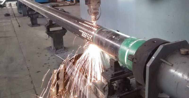
(2) Liner prefabrication: The slotted liner is prefabricated in the factory according to the final design parameters. The slot processing adopts the laser cutting technology to ensure the slot width accuracy (error ±0.02 mm) and the smoothness of the slot edges.
(3) Liner transportation and lowering: The prefabricated slotted liner is transported to the construction site and lowered into the wellbore using a crane. During the lowering process, protective measures are taken to avoid collision and damage to the liner.
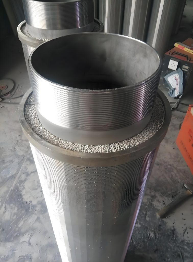
(4) Fixing and sealing: The slotted liner is fixed at the designated position in the wellbore using centralizers, and the gap between the liner and the wellbore is sealed with cement to prevent sand from entering the wellbore from the gap.
(5) Well completion testing: After the installation is completed, a well completion test is carried out, including water yield testing, sand content testing, and pressure testing, to verify the sand control effect and flow performance of the slotted liner.
5.4 Application Effect Evaluation
After the completion of the sand control transformation, the water well has been in service for 1 year, and the application effect is evaluated through on-site monitoring and testing.
5.4.1 Sand Control Effect Evaluation
The sand content in the produced water is tested monthly. The test results show that the average sand content is 0.03%, which is less than the allowable limit of 0.05%. During the 1-year service period, there is no obvious sand accumulation in the wellbore, and the submersible pump operates normally without abrasion. This indicates that the optimized slotted liner has good sand control effect.
5.4.2 Flow Performance Evaluation
The water yield of the well is tested quarterly. The test results show that the average water yield is 152 m³/h, which is significantly higher than the water yield before transformation (80 m³/h) and meets the design requirement of 150 m³/h. The pressure drop of the slotted liner is tested to be 0.7 MPa, which is within the allowable range. This indicates that the optimized slotted liner has good flow performance.
5.4.3 Economic Benefit Evaluation
The economic benefit of the project is evaluated from the aspects of transformation cost, maintenance cost, and water yield increase. The results show that: (1) The total transformation cost of the well is 80,000 yuan, including the cost of the optimized slotted liner (50,000 yuan) and the installation cost (30,000 yuan); (2) Before the transformation, the annual maintenance cost of the well (including the replacement of the submersible pump and well cleaning) was about 40,000 yuan. After the transformation, the annual maintenance cost is reduced to 5,000 yuan, saving 35,000 yuan in maintenance costs per year; (3) The water yield increased by 72 m³/h after the transformation. Based on the water price of 2 yuan/m³ and the annual operation time of 300 days (7200 hours), the annual additional water revenue is 72 × 7200 × 2 = 1,036,800 yuan. Comprehensive calculation shows that the investment recovery period of the sand control transformation project is about 0.08 years (less than 1 month), which has significant economic benefits.
In addition, the optimized slotted liner has good durability. During the 1-year service period, no corrosion, deformation, or damage of the liner was found, which reduces the frequency of well maintenance and further improves the economic benefits of the project. The successful application of the optimized slotted liner in this project also provides a reference for the sand control transformation of similar water wells in the region, which has certain promotional value.
6. Conclusion and Prospect
6.1 Main Conclusions
This paper focuses on the design optimization of slotted liners for sand control in water wells, and conducts in-depth research on the theoretical basis, key design parameters, optimization methods, numerical simulation, and engineering application. The main conclusions are summarized as follows:
(1) The sand control performance of slotted liners is comprehensively affected by liner material properties, sand retention mechanisms (mechanical sieving, sand bridge formation, particle deposition), flow resistance principles (frictional resistance, local resistance at slots, sand deposition resistance), and formation parameters (sand particle size distribution, aquifer porosity and permeability, formation pressure). Among them, the median particle size of formation sand determines the reasonable range of slot width, and the formation pressure is the core factor affecting the selection of liner material and thickness.
(2) Key design parameters of slotted liners (slot width, slot density, slot shape, slot arrangement, liner thickness and material) have significant coupling effects on sand control efficiency, flow performance and structural strength. Rectangular slots with rounded corners and staggered arrangement are optimal choices for balancing sand control effect and flow performance; the slot width should be controlled within 1.5-2.5 times the median particle size (d50) of formation sand, and the slot density needs to be optimized based on the structural strength limit of the liner material.
(3) A multi-factor coupling optimization method integrating theoretical analysis, numerical simulation and experimental testing is proposed. This method can effectively balance the three core objectives of sand control efficiency, flow performance and structural strength. The finite element model established by ANSYS and the CFD model established by Fluent can accurately simulate the structural stress distribution and flow field characteristics of slotted liners, providing a reliable technical basis for parameter optimization.
(4) The engineering case verification shows that the optimized slotted liner designed by the proposed method has excellent practical application effects. After the transformation of the water well in the loose sand aquifer, the average sand content in the produced water is 0.03% (lower than the allowable limit of 0.05%), the water yield is increased from 80 m³/h to 152 m³/h, and the investment recovery period is less than 1 month. It has significant economic benefits and promotional value for similar projects.
6.2 Research Limitations
Although this paper has achieved certain research results, there are still some limitations that need to be improved in future research:
(1) The research scope is mainly focused on loose sand aquifers and gravel aquifers, and the adaptability research of slotted liners in special aquifers (such as fractured aquifers, karst aquifers) is insufficient. The sand control mechanism and design parameter requirements of slotted liners in special aquifers are quite different from those in loose sand aquifers, which need to be further explored.
(2) The numerical simulation and experimental testing in this paper are carried out under static formation conditions. In actual engineering, the formation may have dynamic changes (such as formation settlement, water level fluctuation), which will affect the long-term service performance and structural stability of slotted liners. The relevant research on the adaptability of optimized slotted liners to dynamic formation conditions is lacking.
(3) The multi-factor coupling optimization method proposed in this paper relies on manual iteration and verification to a certain extent. The integration of intelligent optimization algorithms (such as genetic algorithm, particle swarm optimization) and numerical simulation models has not been fully realized, resulting in limited optimization efficiency.
6.3 Future Research Prospects
In view of the research limitations and the development needs of water well sand control technology, the future research directions are proposed as follows:
(1) Expand the research scope to special aquifers. Carry out in-depth research on the sand control mechanism of slotted liners in fractured aquifers and karst aquifers, establish targeted design optimization models, and improve the adaptability of slotted liner sand control technology to different aquifer types.
(2) Strengthen the research on dynamic formation conditions. Through indoor physical simulation and numerical simulation, simulate the dynamic changes of the formation (such as formation settlement, water level fluctuation), study the long-term service performance and structural stability of slotted liners under dynamic conditions, and propose corresponding reinforcement and maintenance strategies.
(3) Develop an intelligent design system for slotted liners. Integrate intelligent optimization algorithms, numerical simulation software and engineering database to build an intelligent design platform. Realize the automatic matching and optimization of design parameters according to formation conditions and engineering requirements, and improve the design efficiency and reliability.
(4) Explore new materials and new structures of slotted liners. Research and develop high-performance composite materials (such as carbon fiber-reinforced composites) with better corrosion resistance and mechanical properties; explore new slot structures (such as variable-width slots, curved slots) to further improve sand control efficiency and flow performance.
(5) Strengthen long-term on-site monitoring and data accumulation. Carry out long-term tracking and monitoring of water wells using optimized slotted liners, collect data on sand content, water yield, liner status and other indicators, establish a long-term performance database, and provide data support for the continuous optimization and improvement of slotted liner design technology.
Related posts

September 14, 2025
August 22, 2023

April 26, 2023

April 30, 2018
April 26, 2018
February 27, 2018

February 14, 2018
January 31, 2018